
Description
Hard-Numbers: Technical Specifications
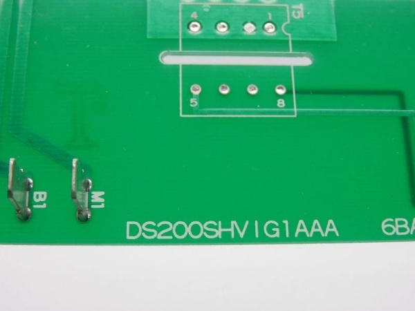
- Functional Acronym: SHVI (Servo High Voltage Interface)
- Group Number: G1 (Group 1 variant)
- Revision: AAA (Board Revision A, Artwork Revision A, Functional Revision A)
- Core Location: Control Core (R> processor rack) – varies by system configuration
- Voltage Capability: High voltage servo drive capability (typically 125 V DC or higher, varies by application)
- Servo Interfaces: Multiple high voltage servo control interfaces
- Command Output: High voltage servo valve drive outputs
- Feedback Input: Multiple feedback input channels (LVDT, resolver, or encoder feedback)
- Position Feedback: LVDT (Linear Variable Differential Transformer) inputs for position sensing
- Signal Conditioning: High voltage signal conditioning and isolation
- Gain/Offset Adjustment: Potentiometers for servo loop tuning
- Trip Function: Integrated high voltage trip output for emergency actuator shutdown
- Isolation: Enhanced galvanic isolation for high voltage applications
- LED Indicators: LED indicators for servo status, fault conditions, and feedback status
- Power Requirements: High voltage power supply input (typically 125 V DC or higher)
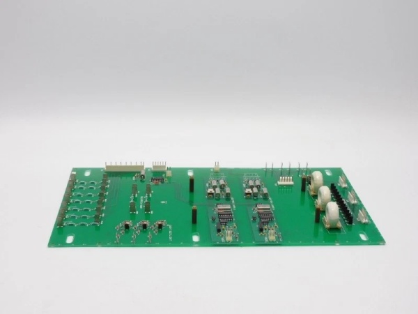
- Dimensions: Standard Mark V board form factor (typically 3″ H × 11.5″ W)
- PCB Coating: Normal coating (non-conformal)
- Manual: GEH-6205 (Servo High Voltage Interface Board Manual)

The Real-World Problem It Solves
The Mark V control system requires high voltage servo drive capability for controlling large actuators with high-force requirements such as large fuel valves, steam control valves, or hydraulic actuators used in heavy-duty turbine applications. Standard servo boards operating at lower voltage levels (typically 24 V DC) lack the drive power to operate these high-force actuators effectively. The DS200SHVIG1AAA (Servo High Voltage Interface Board – Group 1, Revision AAA) provides the high voltage drive capability required for these applications, converting commands from the R> processor into high voltage servo valve drive signals while processing position feedback from LVDTs or other feedback devices. This board enables closed-loop servo control of high-power actuators with the precision required for efficient turbine operation. The revision AAA represents the initial implementation of this high voltage interface board, providing the foundation for high-power servo control in Mark V systems.
Where you’ll typically find it:
- Control Core (R> processor rack) – varies by system configuration
- Large gas turbines with high-force fuel valve actuators
- Steam turbine control systems with large steam control valves
- Heavy-duty hydraulic servo applications
- Applications requiring high voltage servo drive capability
- Turbines with high-force actuators requiring elevated voltage drive
Bottom line: High voltage servo interface for high-power actuators—Group 1 variant, revision AAA configuration, enabling precise position control of large fuel valves, steam valves, and hydraulic actuators requiring elevated voltage drive.
Hardware Architecture & Under-the-Hood Logic
The DS200SHVIG1AAA (Group 1, Revision AAA) is the high voltage servo interface board for the Mark V control system. This board is specifically designed to provide high voltage servo drive capability for controlling large actuators with high-force requirements. The board receives digital position commands from the R> processor and converts these commands into high voltage servo valve drive signals (typically 125 V DC or higher). Position feedback from LVDTs, resolvers, or encoders is conditioned and processed to provide accurate position information for closed-loop control. The servo loop compares commanded position with actual position and adjusts high voltage servo output to minimize position error. Enhanced isolation barriers protect the control system from the high voltage environment. The revision AAA design represents the initial implementation of this high voltage interface board, establishing the fundamental architecture for high-power servo control in Mark V systems.
Signal flow:
- R> processor issues digital position command to SHVI
- Command conversion circuitry generates high voltage servo drive output (125 V DC+)
- Servo valve receives high voltage drive signal and actuates hydraulic system
- Hydraulic system drives large actuator (fuel valve, steam valve, etc.)
- Actuator position changes are detected by position feedback device (LVDT/resolver/encoder)
- LVDT excitation circuitry provides AC excitation to LVDT primary
- Feedback conditioning circuitry processes feedback signals
- Position feedback returns to servo loop for error calculation
- Servo loop calculates position error and adjusts high voltage servo output accordingly
- Gain and offset potentiometers allow servo loop tuning
- Integrated trip function provides emergency actuator shutdown
- Enhanced galvanic isolation protects control system from high voltage
- LED indicators display servo status, fault conditions, and feedback status
- High voltage power supply provides drive capability for large actuators
- Board operates in control core with R> processor redundancy
GE DS200SHVIG1AAA
Field Service Pitfalls: What Rookies Get Wrong
Treating SHVI as standard voltage servo board causes installation errorsMixing up high voltage and standard servo boards. I’ve seen technicians attempting to replace SHVI with standard voltage SDCI or SBCA boards, causing actuator failures due to insufficient drive voltage.
- Field Rule: Always verify board type before installation. SHVI is Servo High Voltage Interface—requires high voltage drive capability. Check board label for “SHVI” designation. Verify application requires high voltage servo drive. Never assume standard servo boards can replace SHVI—high voltage applications require high voltage drive.
Improper high voltage safety precautions cause serious injuryNot following high voltage safety procedures. I’ve seen technicians servicing SHVI boards without proper high voltage precautions, exposing themselves to dangerous voltage levels.
- Field Rule: Always follow high voltage safety procedures when servicing SHVI. Verify power is de-energized before touching any connections. Use insulated tools rated for high voltage applications. Wear appropriate PPE including high voltage gloves if required. Follow lockout/tagout procedures. Verify voltage is zero with multimeter before proceeding. Never work on energized high voltage circuits—high voltage can cause serious injury or death.
Incorrect LVDT calibration causes position error and valve driftIncorrect LVDT scaling or zero adjustment. I’ve seen technicians replacing SHVI boards but not calibrating LVDT feedback, causing large actuators to drift or fail to reach commanded position.
- Field Rule: Always calibrate LVDT feedback after SHVI replacement. Verify LVDT zero position corresponds to actual actuator zero. Check LVDT full-scale position matches actuator full travel. Adjust LVDT scaling potentiometers if required. Test position accuracy across entire range. Large actuators require precise calibration—small errors cause significant position deviations. Never assume LVDT calibration is correct—calibrate after every SHVI change.
Overlooking high voltage isolation integrity causes equipment damageCompromising isolation barriers. I’ve seen technicians damaging isolation components or creating unintended connections, causing control system damage from high voltage transients.
- Field Rule: Verify isolation integrity is intact. Check isolation resistance between high voltage side and control side. Measure isolation voltage rating—ensure it matches system requirements. Confirm no unintended connections exist between isolated sides. Never compromise isolation barriers—high voltage transients destroy control electronics.
Misadjusting servo loop gain causes violent actuator oscillationIncorrect gain potentiometer settings. I’ve seen technicians setting gain too high on high-power actuators, causing violent oscillation that can damage equipment or cause unsafe conditions.
- Field Rule: Adjust servo loop gain carefully, especially on high-power actuators. High-force actuators require conservative gain settings to prevent violent oscillation. Start with very low gain setting, gradually increase while monitoring response. If oscillation occurs, reduce gain immediately. High-power oscillations are dangerous—never use high gain settings on initial commissioning.
Forgetting to verify high voltage drive output causes actuator failureNot measuring high voltage servo drive. I’ve seen technicians assuming drive is working without verifying actual high voltage output, discovering drive failures only when actuator fails to move.
- Field Rule: Measure high voltage servo drive output after installation. Verify drive voltage matches servo valve specifications (typically 125 V DC or higher). Check for open or short circuits in servo valve coils. Test drive voltage variation with command changes. Use appropriate multimeter rated for high voltage measurements. Never assume high voltage drive is correct—verify actual output with proper test equipment.
Confusing SHVI with other high voltage boards causes installation errorsMixing up high voltage board types. I’ve seen technicians confusing SHVI with other high voltage Mark V boards, causing incompatible interfaces and control failures.
- Field Rule: Clearly identify SHVI vs. other high voltage boards. SHVI is Servo High Voltage Interface—different from other high voltage boards (e.g., power supply boards, trip boards). Check board label for “SHVI” designation. Consult GEH-6205 manual for SHVI-specific configuration. Never assume all high voltage boards are identical—verify board type matches application requirements.
Skipping high voltage circuit verification causes latent faultsNot testing high voltage circuits thoroughly. I’ve seen technicians not verifying high voltage isolation and drive capability, discovering issues only during full-load operation.
- Field Rule: Verify all high voltage circuits after SHVI installation. Test isolation resistance between high voltage side and control side. Measure high voltage drive output across full range. Verify isolation components are intact. Use high voltage megger if required to test isolation integrity. Never assume high voltage circuits are correct—verify isolation and drive capability thoroughly.
Commercial Availability & Pricing Note
Please note: The listed price is for reference only and is not binding. Final pricing and terms are subject to negotiation based on current market conditions and availability.


