
Description
Key Technical Specifications
-
Model Number: DS200SDCIG1AFB
-
Manufacturer: General Electric
-
Input Voltage: 90-264 Vac, 47-63 Hz
-
Output Voltage: 24 Vdc ±2 % (logic), up to 20 A
-
Contactor Outputs: 2 Form-C relays, 250 Vac / 30 Vdc, 5 A resistive
-
CT Burden Switch: SW1, 1 A or 5 A nominal
-
Protection: Over-voltage, under-voltage, over-current, short-circuit, thermal shutdown
-
Fuses: FU1 (line), FU2/FU3 (signal), FU5/FU6 (MOV), all 5×20 mm, LED blown indicators
-
Jumpers: JPI MD (control source), JP2 MA (AC contactor dropout delay)
-
Isolation: 1500 Vac input-to-output, 500 Vdc output-to-ground
-
Operating Temperature: –40 °C to +70 °C
-
Board Size: 160 × 160 × 12 mm, 0.8 kg
- Rack Connectors: J1–J4, 40-pin, hot-pluggable on Mark V backplane
-

DS200SDCCG1AFD
-
Field Application & Problem Solved
A DC2000 drive rack won’t even boot without this board. Out in the field—especially on aging gas compressors or boiler feed pumps—the original SDCI bricks fail because the electrolytics dry out and the 24 Vdc rail collapses. When that happens you lose gate drivers, contactor pick coils, and the Mark V throws “<P>
A DC2000 drive rack won’t even boot without this board. Out in the field—especially on aging gas compressors or boiler feed pumps—the original SDCI bricks fail because the electrolytics dry out and the 24 Vdc rail collapses. When that happens you lose gate drivers, contactor pick coils, and the Mark V throws “<P>
Installation & Maintenance Pitfalls (Expert Tips)
Capacitor age-out is real
Rev AFB boards built before 2010 use 85 °C caps. After 50 k hours at 55 °C they’re toast. If you’re buying surplus, order the cap kit and re-work before install—otherwise you’ll repeat the call-out in six months.
Capacitor age-out is real
Rev AFB boards built before 2010 use 85 °C caps. After 50 k hours at 55 °C they’re toast. If you’re buying surplus, order the cap kit and re-work before install—otherwise you’ll repeat the call-out in six months.
LEDs lie if you’re on generator power
FU1 LED is across the line input; if you’re running on a floating diesel genset the neon won’t strike and you’ll think the fuse is good when it’s blown. Always meter FU1 with power off.
FU1 LED is across the line input; if you’re running on a floating diesel genset the neon won’t strike and you’ll think the fuse is good when it’s blown. Always meter FU1 with power off.
JP2 timing matters on big contactors
Default jumper is 0 ms. On 480 Vac vacuum contactors you’ll weld the tips. Move JP2 to the 100 ms pad so the DC link bleeds below 50 V before the coil drops out—saves you a $2 k contactor.
Default jumper is 0 ms. On 480 Vac vacuum contactors you’ll weld the tips. Move JP2 to the 100 ms pad so the DC link bleeds below 50 V before the coil drops out—saves you a $2 k contactor.
Tighten CT screws once, then again after 24 h
SW1 burden resistors get hot. A loose CT screw raises resistance, fools the regulator into thinking load is low, and the drive overspeeds on start. Torque to 1.2 N·m and hit it again after the first thermal cycle.
SW1 burden resistors get hot. A loose CT screw raises resistance, fools the regulator into thinking load is low, and the drive overspeeds on start. Torque to 1.2 N·m and hit it again after the first thermal cycle.
DS200SDCCG1AFD
Technical Deep Dive & Overview
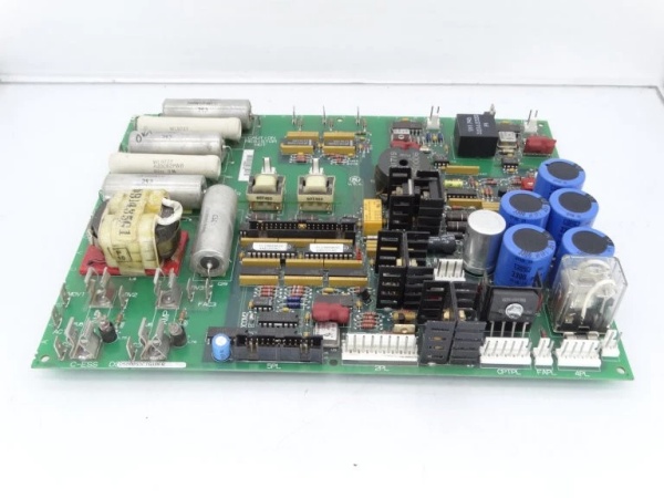
The DS200SDCIG1AFB is a switch-mode front-end plus housekeeping card. A two-stage EMI filter feeds a UC3844 current-mode supply that generates 24 Vdc at up to 20 A. An on-board housekeeping converter keeps the LEDs alive even when the drive is off as long as line power is present. Two relays (K1, K2) with varistor snubbers provide the “contactor OK” interlock to the Mark V. Burden resistors R1–R6 are switched by SW1 so the same CT secondaries can be used for 1 A or 5 A metering. All control signals route through the 40-pin J3/J4 headers to the SDCC board; the SDCI contains no micro, just comparators and drivers—so it’s hot-swappable without a download.
The DS200SDCIG1AFB is a switch-mode front-end plus housekeeping card. A two-stage EMI filter feeds a UC3844 current-mode supply that generates 24 Vdc at up to 20 A. An on-board housekeeping converter keeps the LEDs alive even when the drive is off as long as line power is present. Two relays (K1, K2) with varistor snubbers provide the “contactor OK” interlock to the Mark V. Burden resistors R1–R6 are switched by SW1 so the same CT secondaries can be used for 1 A or 5 A metering. All control signals route through the 40-pin J3/J4 headers to the SDCC board; the SDCI contains no micro, just comparators and drivers—so it’s hot-swappable without a download.


