
Description
Hard-Numbers: Technical Specifications
- Functional Acronym: SDCC (Servo Drive Control Card)
- Group Number: G4 (Group 4 variant)
- Revision: A (Board Revision A)
- Core Location: Control Core (R> processor rack) – varies by system configuration
- Drive Interfaces: Multiple servo drive control interfaces (varies by Group 4 configuration)
- Output Type: Analog and digital signals to servo drives (typically ±10 V analog command + digital enable/fault signals)
- Input Feedback: Analog feedback from servo drives (speed, torque, current, position)
- Control Modes: Speed control, torque control, position control (varies by application)
- Enable/Disable Signals: Digital control signals for drive enable and fault reset
- Fault Monitoring: Fault input monitoring from servo drives
- Isolation: Galvanic isolation between control system and servo drives
- LED Indicators: LED indicators for drive status, fault conditions, and communication status
- Power Requirements: Typically 24 V DC from control system power supply
- Dimensions: Standard Mark V board form factor (typically 3″ H × 11.5″ W)
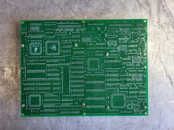
- PCB Coating: Normal coating (non-conformal)
- Manual: GEH-6218 (Drive Control Board Manual)

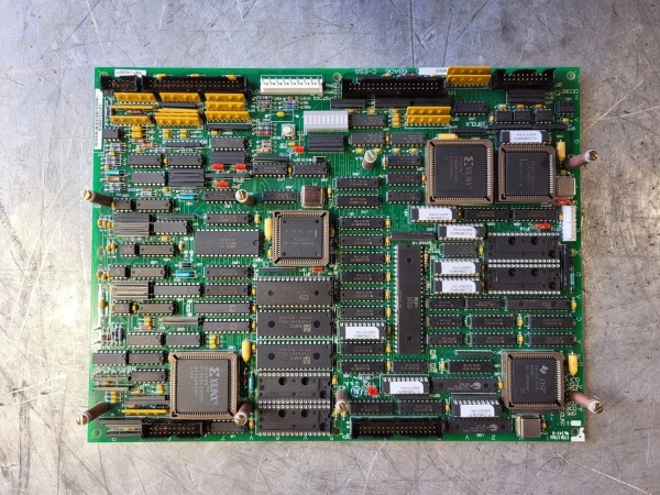
GE DS200SDCCG4A
The Real-World Problem It Solves
The Mark V control system requires precise control of servo motors driving auxiliary equipment such as fuel pumps, lube oil pumps, hydraulic pumps, and other motor-driven devices critical to turbine operation. The DS200SDCCG4A (Drive Control Board – Group 4, Revision A) provides the control interface between the Mark V control system and servo drives, converting commands from the R> processor into drive-compatible analog and digital signals while monitoring drive status and faults. This board enables closed-loop control of servo motor speed, torque, or position, ensuring auxiliary equipment operates at required levels for optimal turbine performance. The Group 4 configuration provides specific drive interface options tailored to particular applications or servo drive manufacturers, while the revision A design represents the initial implementation of this board type. Without this board, the Mark V control system would lack the ability to precisely control servo-driven auxiliary equipment, relying on less precise on/off or simple variable speed control methods.
Where you’ll typically find it:
- Control Core (R> processor rack) – varies by system configuration
- Gas turbine control systems with servo-driven auxiliary equipment
- Steam turbine control systems with servo-driven pumps
- Applications requiring precise servo motor control
- Systems with fuel pump, lube oil pump, or hydraulic pump servo drives
- Applications using Group 4 drive interface configuration
Bottom line: Control interface for servo motors driving auxiliary equipment—Group 4 variant, revision A configuration, enabling precise speed/torque/position control of critical auxiliary devices.
Hardware Architecture & Under-the-Hood Logic
The DS200SDCCG4A (Group 4, Revision A) is the servo drive control interface board for the Mark V control system. This Group 4 variant provides specific drive interface options tailored to particular applications or servo drive manufacturers, differing from other SDCC groups in connector configuration, signal types, or drive compatibility. The board receives speed/torque/position commands from the R> processor and converts these commands into drive-compatible analog signals (typically ±10 V speed reference) and digital control signals (enable, fault reset, direction). Servo drive feedback signals (speed, torque, current, position) are monitored and reported back to the R> processor for closed-loop control. The board provides galvanic isolation between the sensitive control electronics and the potentially noisy electrical environment of servo drives, protecting the control system from voltage spikes and electrical noise. The Group 4 configuration may include specific analog output ranges, digital I/O configurations, or drive communication protocols optimized for particular servo drive types or manufacturers.
Signal flow:
- R> processor issues speed/torque/position command to SDCC
- Command conversion circuitry generates drive-compatible analog output (±10 V)
- Digital control signals (enable, direction, fault reset) output to servo drive
- Servo drive receives command signals and drives servo motor accordingly
- Servo drive feedback signals (speed, torque, current, position) return to SDCC
- Feedback conditioning circuitry prepares signals for R> processor input
- Fault signals from servo drive are monitored and reported to R> processor
- Galvanic isolation separates control system ground from servo drive ground
- LED indicators display drive status, fault conditions, and communication status
- Group 4 configuration provides specific signal types and ranges
- Multiple drive interfaces may be supported (varies by application)
- Board operates in control core with R> processor redundancy
- Connector interfaces with R> processor for command and feedback signals
- Terminal blocks provide field wiring termination to servo drives
- Revision A represents initial implementation of Group 4 SDCC board
GE DS200SDCCG4A
Field Service Pitfalls: What Rookies Get Wrong
Confusing Group 4 SDCC with other group variants causes installation errorsMixing up SDCC board groups. I’ve seen technicians replacing Group 4 SDCC with other group boards, causing incompatible drive interfaces and control failures.
- Field Rule: Always verify SDCC group number before installation. Group 4 SDCC boards have specific drive interfaces different from other groups. Check board label for “G4” designation. Compare original board group with replacement board. Consult GEH-6218 manual for group-specific differences. Never assume all SDCC boards are interchangeable—verify group number matches application requirements.
Assuming Group 4 analog output ranges match other groups causes drive errorsNot understanding Group 4-specific analog output ranges. I’ve seen technicians expecting Group 4 analog outputs to match other groups, causing servo drive speed reference errors.
- Field Rule: Understand Group 4 may have different analog output ranges. Group 4 may use ±10 V, 0-10 V, 4-20 mA, or other ranges depending on application. Check servo drive specifications for required command range. Verify SDCC output range matches drive requirements. Measure analog output with multimeter during operation. Never assume Group 4 output range matches other groups—verify Group 4-specific parameters.
Mixing up analog command and feedback connections causes control instabilityConfusing analog output and input connections. I’ve seen technicians connecting servo drive feedback to SDCC analog output and vice versa, causing complete control failure.
- Field Rule: Clearly identify analog command and feedback connections. Analog outputs from SDCC go to servo drive command inputs. Analog feedback from servo drive returns to SDCC feedback inputs. Label all analog signal wires clearly. Verify connections with wiring diagrams. Test command output with multimeter—should vary with R> processor command. Never mix up command and feedback—reverse connections prevent closed-loop control.
Overlooking Group 4-specific enable/disable logic causes drive non-responseNot understanding Group 4 enable/disable signal behavior. I’ve seen technicians expecting enable logic to match other groups, causing drives to remain disabled.
- Field Rule: Understand Group 4-specific enable/disable signal requirements. Group 4 may use different enable logic (active high, active low, dual enable) than other groups. Check servo drive enable signal specifications. Verify SDCC digital output logic matches drive requirements. Test enable function with manual command if possible. Never assume enable logic matches other groups—verify Group 4-specific requirements.
Forgetting to verify fault signal polarity causes missed fault detectionReversing fault signal polarity. I’ve seen technicians connecting fault signals with wrong polarity, causing SDCC to miss servo drive faults or report false faults.
- Field Rule: Verify fault signal polarity matches system configuration. Fault inputs may be active high or active low. Check servo drive fault output specification. Document original fault signal configuration before removal. Test fault response by simulating fault condition. Never assume fault signal polarity—verify correct polarity.
Improper grounding causes erratic drive behaviorNot establishing proper ground reference. I’ve seen technicians causing ground loops or floating grounds, causing erratic servo drive behavior or communication failures.
- Field Rule: Establish proper ground reference for servo drives. Verify servo drive ground connects to correct SDCC ground terminal. Check isolation barriers are intact—no unintended connections between isolated sides. Measure ground potential difference between control system and servo drive. Never compromise isolation barriers—ground loops cause erratic operation.
Skipping Group 4 signal verification causes latent faultsNot testing Group 4-specific signal paths. I’ve seen technicians testing based on other group knowledge, missing Group 4-specific issues.
- Field Rule: Verify all Group 4 signal paths after installation. Test analog command output varies with R> processor command. Verify feedback signals from servo drive match actual motor operation. Test enable/disable function. Simulate fault condition and verify fault detection. Use Mark V diagnostic tools to confirm all signals are operational. Never assume Group 4 signals match other groups—test Group 4-specific functions.
Forgetting to update maintenance records with Group 4 information causes future confusionNot documenting Group 4 board installation. I’ve seen technicians not recording Group 4 SDCC replacement, causing confusion during future maintenance.
- Field Rule: Update maintenance records with Group 4 SDCC information. Document board model (DS200SDCCG4A), revision A, installation date. Note Group 4-specific configuration differences. Record any compatibility issues encountered. Store photographs of original and new board configurations. Never leave records outdated—future service depends on accurate documentation.
Commercial Availability & Pricing Note
Please note: The listed price is for reference only and is not binding. Final pricing and terms are subject to negotiation based on current market conditions and availability.


