
Description
Hard-Numbers: Technical Specifications
- Functional Acronym: SBCA (Servo Board)
- Group Number: G1
- Revision: A (Board Revision A)
- Core Location: Control Core (R> processor rack) – typically Location 1 or 2
- Servo Loops: Multiple independent servo control loops (typically 2-4 per board)
- Position Feedback: LVDT (Linear Variable Differential Transformer) inputs for position sensing
- Output Type: Analog current output to servo valve coils (typically ±20 mA or similar)
- Input Reference: Analog voltage or current command from R> processor
- Feedback Type: LVDT AC excitation and demodulated DC position signals
- Gain Adjustment: Potentiometers for servo loop gain tuning
- Offset Adjustment: Potentiometers for servo loop offset adjustment
- LED Indicators: LED indicators for servo status and fault conditions
- Power Requirements: Typically 24 V DC or 125 V DC from control system power supply
- Dimensions: Standard Mark V board form factor (typically 3″ H × 11.5″ W)
- PCB Coating: Normal coating (non-conformal)

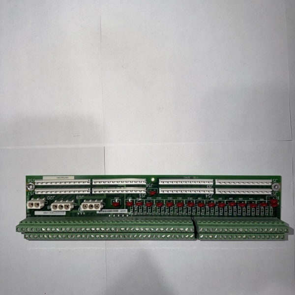
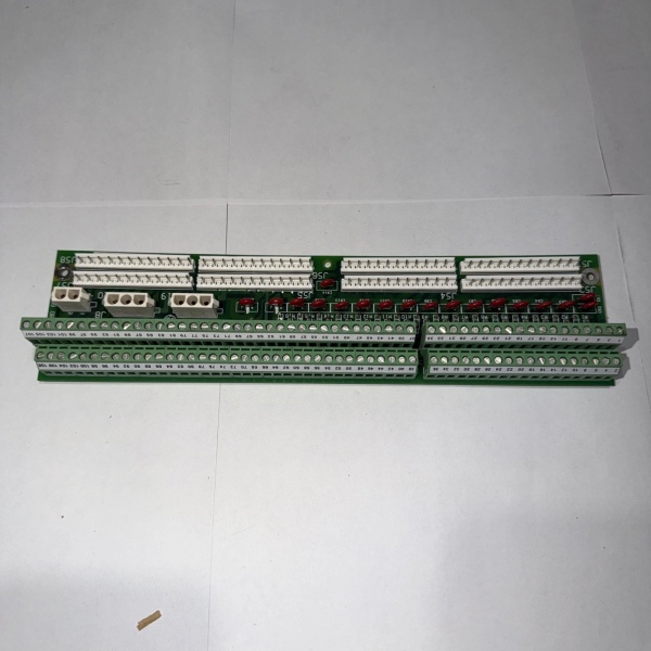
DS200SBCAG1A
The Real-World Problem It Solves
The Mark V control system requires precise position control of fuel valves, steam valves, inlet guide vanes (IGVs), and other critical actuators for efficient turbine operation. The DS200SBCAG1A (Servo Board – Revision A) provides this control by implementing closed-loop servo control that drives electrohydraulic servo valves based on position commands from the R> governor processor and actual position feedback from LVDTs (Linear Variable Differential Transformers). This board converts digital position commands from the control system into analog servo valve drive signals, compares actual position from LVDT feedback with commanded position, and adjusts servo valve drive to maintain precise actuator positioning. Without this board, precise throttle control of fuel valves or steam valves would be impossible, leading to inefficient operation, unstable speed/load control, or potential equipment damage from improper valve positioning.
Where you’ll typically find it:
- Control Core (R> processor rack) – Location 1 or 2
- Gas turbine control systems with fuel valve servo control
- Steam turbine control systems with steam valve servo control
- Applications with inlet guide vane (IGV) position control
- Systems requiring precise actuator position control
- Turbines with electrohydraulic servo valve actuators
Bottom line: Precise servo position control for critical turbine actuators—fuel valves, steam valves, IGVs—enabling efficient and stable turbine operation.
Hardware Architecture & Under-the-Hood Logic
The DS200SBCAG1A (Revision A) is the servo position control board for the Mark V control system. This board implements closed-loop servo control loops for precise actuator positioning, driving electrohydraulic servo valves based on commands from the R> governor processor and actual position feedback from LVDTs. Each servo loop consists of a command input from the R> processor (typically a voltage or current reference signal), a servo valve drive output (typically a current output to servo valve coils), and LVDT position feedback. The servo loop compares commanded position with actual position from LVDT feedback and adjusts servo valve drive to minimize position error. Gain and offset potentiometers allow tuning of each servo loop for optimal response. The LVDT excitation circuitry provides AC excitation to LVDT primary windings, while LVDT signal conditioning circuits demodulate LVDT secondary signals to provide DC position feedback. The board typically supports multiple independent servo loops (2-4 per board) for controlling multiple actuators.
Signal flow:
- R> processor issues position command to SBCA (voltage or current reference)
- Servo loop compares command with actual position from LVDT feedback
- Servo loop calculates position error and generates servo valve drive signal
- Servo valve drive output (current signal) drives servo valve coils
- Servo valve adjusts hydraulic flow to move actuator
- Actuator position changes are detected by LVDT
- LVDT excitation circuitry provides AC excitation to LVDT primary
- LVDT secondary signals are demodulated to DC position feedback
- Position feedback returns to servo loop for error calculation
- Servo loop continues adjusting drive until position error approaches zero
- Gain potentiometers adjust servo loop response speed and stability
- Offset potentiometers compensate for zero-point errors
- LED indicators display servo status and fault conditions
- Multiple independent servo loops operate simultaneously
- Board operates in control core with R> processor redundancy
DS200SBCAG1A
Field Service Pitfalls: What Rookies Get Wrong
Improper LVDT calibration causes position error and valve driftIncorrect LVDT scaling or zero adjustment. I’ve seen technicians replacing servo boards but not calibrating LVDT feedback, causing actuators to drift or fail to reach commanded position.
- Field Rule: Always calibrate LVDT feedback after servo board replacement. Verify LVDT zero position corresponds to actual actuator zero. Check LVDT full-scale position matches actuator full travel. Adjust LVDT scaling potentiometers if required. Test position accuracy across entire range. Never assume LVDT calibration is correct—calibrate after every servo board change.
Confusing LVDT primary and secondary windings causes no position feedbackMixing up LVDT connections. I’ve seen technicians connecting LVDT primary and secondary windings incorrectly, causing no position feedback or erratic feedback signals.
- Field Rule: Verify LVDT connections are correct. LVDTs have one primary winding (excitation) and two secondary windings (feedback). Primary winding connects to excitation output from SBCA. Secondary windings connect to feedback inputs. Check LVDT datasheet for proper wiring. Test LVDT output with known displacement. Never guess at LVDT wiring—incorrect wiring prevents position feedback.
Overlooking servo valve coil polarity causes wrong direction responseReversing servo valve coil connections. I’ve seen technicians connecting servo valve coils backward, causing actuators to move in opposite direction of command.
- Field Rule: Verify servo valve coil polarity is correct. Servo valve coils have polarity—reversing causes opposite direction response. Check servo valve datasheet for proper polarity. Test servo response with small command after installation. If actuator moves opposite to command, swap coil connections. Never assume coil polarity—verify direction of response.
Misadjusting servo loop gain causes oscillation or sluggish responseIncorrect gain potentiometer settings. I’ve seen technicians setting gain too high (causing oscillation) or too low (causing sluggish response), making servo control unstable or unresponsive.
- Field Rule: Adjust servo loop gain carefully. Start with low gain setting, gradually increase until response is adequate without oscillation. Monitor actuator response during gain adjustment. If oscillation occurs, reduce gain. Document final gain settings. Never set gain based on guess—adjust systematically and verify response.
Forgetting to verify servo valve drive current causes valve failureNot measuring servo valve drive output. I’ve seen technicians assuming servo drive is working without measuring current, discovering servo valve coil failures only when actuator fails to move.
- Field Rule: Measure servo valve drive current after installation. Verify drive current matches servo valve specifications (typically ±20 mA range). Check for open or short circuits in servo valve coils. Test drive current variation with command changes. Never assume drive current is correct—verify actual output with multimeter.
Mixing up servo loops causes wrong actuator controlConnecting servo outputs to wrong actuators. I’ve seen technicians confusing which servo loop controls which actuator, causing incorrect valve responses to commands.
- Field Rule: Clearly identify which servo loop controls which actuator. Document servo loop assignments before board removal. Label each servo output with corresponding actuator. Verify servo loop to actuator mapping after installation. Test each actuator individually to confirm correct assignment. Never assume servo loop numbering matches actuator numbering—verify mapping.
Skipping servo board compatibility checks causes installation errorsInstalling revision A without verifying compatibility. I’ve seen technicians replacing later SBCA revisions with revision A boards, causing compatibility issues with system configuration.
- Field Rule: Verify revision A compatibility before installation. Revision A may have different capabilities than later revisions. Check if system requires later revision features. Compare original board revision with replacement board. Consult GEH-6199 manual for revision compatibility. Check for any engineering change notices (ECNs). Never assume revision A matches later revisions—verify compatibility first.
Neglecting to test emergency trip function causes protection failureNot verifying servo trip function. I’ve seen technicians replacing servo boards but not testing emergency trip, discovering trip failures during actual emergency conditions.
- Field Rule: Always test emergency trip function after servo board installation. Verify servo trip command causes actuator to move to fail-safe position. Test trip response time. Check that trip overrides normal servo control. Document trip function test results. Never assume trip function works—verify emergency response before placing in service.
Forgetting to document gain and offset settings causes retuning difficultyNot recording potentiometer settings. I’ve seen technicians replacing servo boards without documenting original gain and offset settings, requiring complete retuning from scratch.
- Field Rule: Document all potentiometer settings before removal. Record gain and offset potentiometer positions for each servo loop. Photograph potentiometer settings. Measure and record actual resistance values if possible. Compare settings on new board with original. Never replace board without documentation—retuning from scratch wastes time and risks instability.
Commercial Availability & Pricing Note
Please note: The listed price is for reference only and is not binding. Final pricing and terms are subject to negotiation based on current market conditions and availability.


