
Description
Hard-Numbers: Technical Specifications
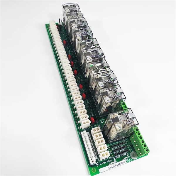
- Functional Acronym: RTBA
- Group Number: G2 (Group 2 variant)
- Revision: HC (Board Revision H, Artwork Revision C)
- Core Location: Control Core (R> processor rack) – varies by system configuration
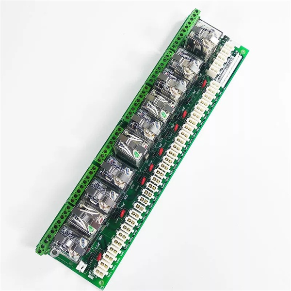
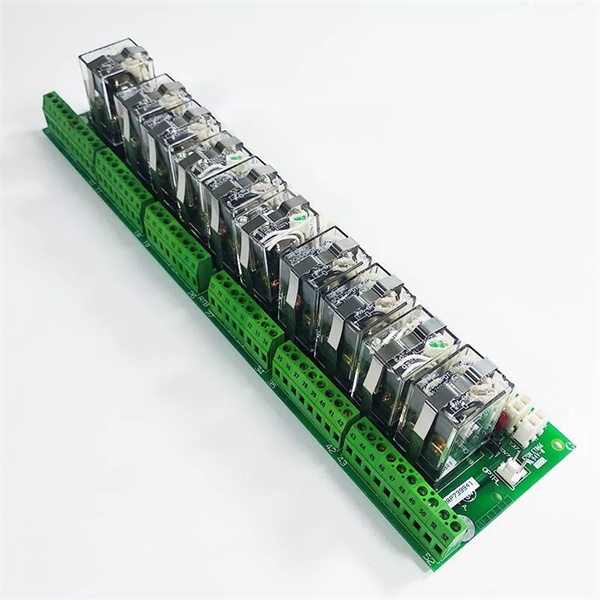
- Relay Outputs: Multiple electromechanical relay outputs for field device control (Group 2 configuration)
- Relay Inputs: Multiple digital inputs via relay contact closure sensing (Group 2 configuration)
- Terminal Blocks: Multiple terminal blocks for field wiring
- Connectors: Multiple connectors for interfacing with control boards
- Relay Types: Typically 24 V DC or 125 V DC coil relays (varies by application)
- Contact Ratings: Varies by relay type (typically 5A at 125 V AC/DC or 250 V AC)
- Isolation: Relay contacts provide galvanic isolation between control system and field devices
- LED Indicators: LED indicators for relay status and input status
- Power Requirements: Typically 24 V DC or 125 V DC from control system power supply
- Dimensions: Standard Mark V board form factor (typically 3″ H × 11.5″ W)
- PCB Coating: Normal coating (non-conformal)
- Manual: GEH-6189 (Relay Terminal Board Manual)

GE DS200RTBAG1AHC
The Real-World Problem It Solves
The Mark V control system requires galvanic isolation between the sensitive control electronics and the harsh electrical environment of field devices. The DS200RTBAG2AHC (Relay Terminal Board – Group 2, Revision HC) provides this isolation through electromechanical relays that interface between control outputs and field device inputs, as well as field device status feedback and control system inputs. This Group 2 variant differs from Group 1 boards in relay configuration, contact arrangement, or I/O capacity, providing alternative interface options for specific application requirements. The board protects the control system from voltage spikes, ground loops, and electrical noise commonly encountered in industrial environments while providing reliable control and monitoring capability for solenoid valves, motor starters, position switches, and other auxiliary devices. The revision HC represents a mature hardware design with potential improvements in relay reliability, contact protection circuits, or component durability.
Where you’ll typically find it:
- Control Core (R> processor rack) – varies by system configuration
- Gas turbine control systems with relay-based field device interfaces
- Steam turbine control cabinets
- Generator control panels
- Applications requiring Group 2 relay configuration
- Systems requiring alternative relay interface arrangements
Bottom line: Galvanically isolated relay interface between Mark V control system and field devices—Group 2 variant, revision HC configuration, providing alternative interface options for specific applications.
Hardware Architecture & Under-the-Hood Logic
The DS200RTBAG2AHC (Group 2, Revision HC) is the relay interface board for the Mark V control system. This Group 2 variant differs from Group 1 RTBA boards in relay configuration, contact arrangement, or I/O capacity, providing alternative interface options for specific application requirements. The board provides electromechanical relay isolation between control outputs/inputs and field devices, protecting sensitive control electronics from harsh electrical environments. Control outputs from the R> processor drive relay coils, which then switch isolated contacts to field devices. Conversely, field device status signals (limit switches, pressure switches, auxiliary contacts) connect through relay contacts or opto-isolators to provide galvanically isolated status feedback to the control system. The Group 2 configuration may include different relay types, different contact arrangements (more NO contacts, different current ratings), or alternative I/O channel arrangements compared to Group 1 boards. The revision HC design incorporates potential improvements in relay contact protection, coil suppression diodes, LED indication reliability, or enhanced isolation barriers.
Signal flow:
- Control outputs from R> processor drive relay coils on RTBA (Group 2 configuration)
- Relay contacts provide isolated control to field devices (solenoid valves, motor starters)
- Field device status (limit switches, pressure switches) connect via relay contacts to RTBA inputs
- Status feedback from field devices routes through isolated contacts to R> processor inputs
- Relay coil suppression diodes protect control outputs from inductive kickback
- Contact protection circuits (RC networks, varistors) protect contacts from arcing
- LED indicators display relay status (energized/de-energized) and input status
- Power supply (24 V DC or 125 V DC) provides coil excitation voltage
- Galvanic isolation separates control system ground from field device ground
- Group 2 relay configuration differs from Group 1 in contact arrangement or I/O capacity
- Revision HC may include improved relay contact materials or protection circuits
- Relay contact ratings vary by application (typically 5A at 125 V AC/DC or 250 V AC)
- Board operates in control core with R> processor redundancy
- Connector interfaces with R> processor for control and status signals
- Terminal blocks provide field wiring termination points
GE DS200RTBAG1AHC
Field Service Pitfalls: What Rookies Get Wrong
Confusing Group 1 and Group 2 RTBA configurations causes installation errorsMixing up Group 1 and Group 2 board variants. I’ve seen technicians replacing Group 2 RTBA with Group 1 boards, causing incorrect I/O configuration and control failures.
- Field Rule: Always verify board group number before installation. Group 1 and Group 2 RTBA boards have different relay configurations. Check board label for “G1” or “G2” designation. Compare original board group with replacement board. Consult GEH-6189 manual for group-specific configuration differences. Never assume all RTBA boards are interchangeable—verify group number matches application requirements.
Assuming Group 2 relay specifications match Group 1 causes compatibility issuesNot understanding Group 2 differences. I’ve seen technicians expecting Group 2 relays to have same ratings as Group 1, causing relay failures or control issues.
- Field Rule: Understand Group 2 may have different relay specifications. Group 2 may use different relay types, contact ratings, or coil voltages. Check relay datasheets for Group 2-specific ratings. Verify contact ratings match field device requirements. Compare coil voltage with system supply. Never assume Group 2 matches Group 1 specifications—verify Group 2-specific parameters.
Forgetting to verify Group 2-specific jumper settings causes configuration errorsMissing Group 2 configuration jumpers. I’ve seen technicians setting jumpers based on Group 1 knowledge, causing incorrect Group 2 operation.
- Field Rule: Verify Group 2-specific jumper settings are correct. Group 2 may have different jumper positions or configuration options. Document original jumper positions before removal. Compare new board jumper configuration with original. Consult GEH-6189 manual for Group 2 jumper descriptions. Never assume Group 2 jumpers match Group 1—verify Group 2-specific settings.
Mixing up Group 2 connector assignments causes signal routing errorsIncorrect Group 2 connector wiring. I’ve seen technicians wiring Group 2 connectors based on Group 1 knowledge, causing signal misrouting.
- Field Rule: Verify Group 2 connector assignments are correct. Group 2 may have different connector pinouts or signal assignments. Check connector labels on Group 2 board. Document which connectors carry which signals. Verify ribbon cables match Group 2 configuration. Never assume Group 2 connectors match Group 1—verify Group 2-specific routing.
Overlooking Group 2 terminal block differences causes wiring errorsNot distinguishing Group 2 terminal layout. I’ve seen technicians wiring Group 2 terminals based on Group 1 memory, causing incorrect field device connections.
- Field Rule: Verify Group 2 terminal block layout matches original. Group 2 may have different terminal arrangements or assignments. Create terminal map before removing original board. Label all wires with terminal IDs. Verify new board terminal positions match original. Never rely on Group 1 experience—document Group 2-specific terminal layout.
Assuming revision HC compatibility without Group 2 verification causes installation failuresInstalling revision HC without checking Group 2 compatibility. I’ve seen technicians verifying revision compatibility but forgetting Group 2-specific requirements, causing installation failures.
- Field Rule: Verify both revision HC compatibility and Group 2 configuration. Revision HC may have Group 2-specific changes. Check for engineering change notices (ECNs) applying to Group 2 revision HC boards. Compare original board revision and group with replacement board. Document any Group 2-specific configuration differences. Never verify revision only—check Group 2 compatibility too.
Skipping Group 2 signal verification causes latent faultsNot testing Group 2-specific signal paths. I’ve seen technicians testing based on Group 1 knowledge, missing Group 2-specific issues.
- Field Rule: Verify all Group 2 signal paths after installation. Test relay outputs with actual field device loads. Verify input status feedback matches field device states. Check Group 2-specific I/O channels are functional. Use Mark V diagnostic tools to confirm all signals are operational. Never assume Group 2 signals match Group 1—test Group 2-specific functions.
Forgetting to update maintenance records with Group 2 information causes future confusionNot documenting Group 2 board installation. I’ve seen technicians not recording Group 2 board replacement, causing confusion during future maintenance.
- Field Rule: Update maintenance records with Group 2 board information. Document board model (DS200RTBAG2AHC), revision HC, installation date. Note Group 2-specific configuration differences. Record any compatibility issues encountered. Store photographs of original and new board configurations. Never leave records outdated—future service depends on accurate documentation.
Commercial Availability & Pricing Note
Please note: The listed price is for reference only and is not binding. Final pricing and terms are subject to negotiation based on current market conditions and availability.


