
Description
Hard-Numbers: Technical Specifications
- Functional Acronym: RTBA
- Group Number: G1
- Revision: HC (Board Revision H, Artwork Revision C)
- Core Location: Control Core (R> processor rack) – typically Location 5 or 6
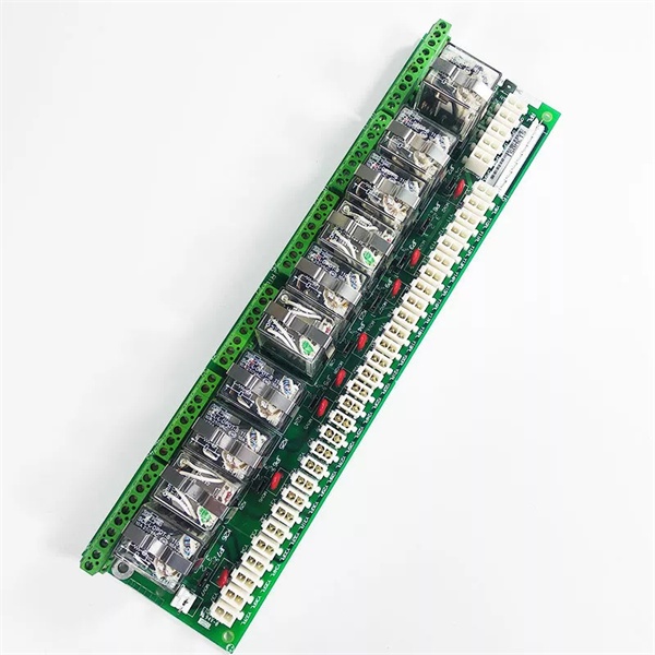
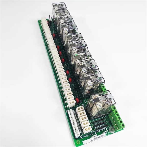
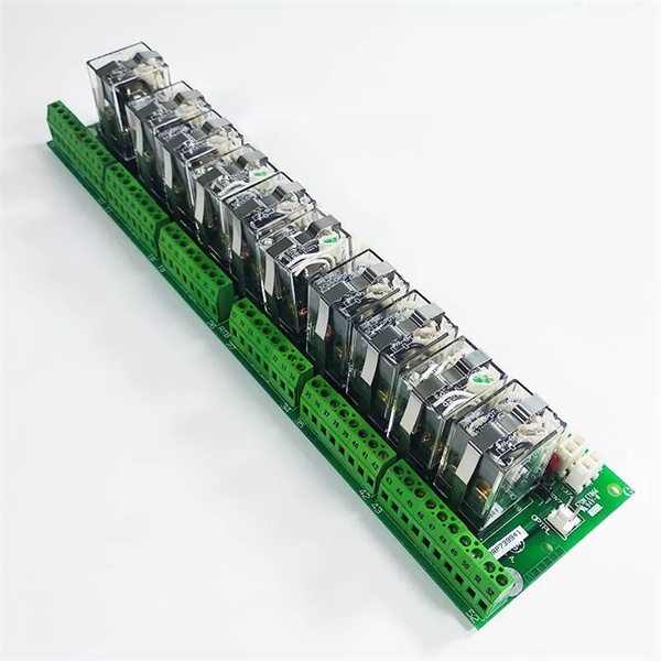
- Relay Outputs: Multiple electromechanical relay outputs for field device control
- Relay Inputs: Multiple digital inputs via relay contact closure sensing
- Terminal Blocks: Multiple terminal blocks for field wiring
- Connectors: Multiple connectors for interfacing with control boards
- Relay Types: Typically 24 V DC or 125 V DC coil relays (varies by application)
- Contact Ratings: Varies by relay type (typically 5A at 125 V AC/DC or 250 V AC)
- Isolation: Relay contacts provide galvanic isolation between control system and field devices
- LED Indicators: LED indicators for relay status and input status
- Power Requirements: Typically 24 V DC or 125 V DC from control system power supply
- Dimensions: Standard Mark V board form factor (typically 3″ H × 11.5″ W)
- PCB Coating: Normal coating (non-conformal)
- Manual: GEH-6189 (Relay Terminal Board Manual)

GE DS200RTBAG1AHC
The Real-World Problem It Solves
The Mark V control system requires galvanic isolation between the sensitive control electronics and the harsh electrical environment of field devices. The DS200RTBAG1AHC (Relay Terminal Board – Revision HC) provides this isolation through electromechanical relays that interface between control outputs and field device inputs, as well as field device status feedback and control system inputs. This board protects the control system from voltage spikes, ground loops, and electrical noise commonly encountered in industrial environments while providing reliable control and monitoring capability for solenoid valves, motor starters, position switches, and other auxiliary devices. The revision HC represents a mature hardware design with potential improvements in relay reliability, contact protection circuits, or component durability over earlier revisions.
Where you’ll typically find it:
- Control Core (R> processor rack) – Location 5 or 6
- Gas turbine control systems with relay-based field device interfaces
- Steam turbine control cabinets
- Generator control panels
- Applications requiring galvanic isolation between control system and field devices
- Systems with multiple solenoid valves or motor starters
Bottom line: Galvanically isolated relay interface between Mark V control system and field devices—revision HC configuration, protecting control electronics while enabling reliable field device control.
Hardware Architecture & Under-the-Hood Logic
The DS200RTBAG1AHC (Revision HC) is the relay interface board for the Mark V control system. This board provides electromechanical relay isolation between control outputs/inputs and field devices, protecting sensitive control electronics from harsh electrical environments. The RTBA board contains multiple relays for control outputs (driving solenoid valves, motor starters, and other field devices) and digital input sensing circuits for monitoring field device status via relay contact closures. Control outputs from the R> processor drive relay coils, which then switch isolated contacts to field devices. Conversely, field device status signals (limit switches, pressure switches, auxiliary contacts) connect through relay contacts or opto-isolators to provide galvanically isolated status feedback to the control system. The revision HC design incorporates potential improvements in relay contact protection, coil suppression diodes, LED indication reliability, or enhanced isolation barriers based on GE engineering change orders.
Signal flow:
- Control outputs from R> processor drive relay coils on RTBA
- Relay contacts provide isolated control to field devices (solenoid valves, motor starters)
- Field device status (limit switches, pressure switches) connect via relay contacts to RTBA inputs
- Status feedback from field devices routes through isolated contacts to R> processor inputs
- Relay coil suppression diodes protect control outputs from inductive kickback
- Contact protection circuits (RC networks, varistors) protect contacts from arcing
- LED indicators display relay status (energized/de-energized) and input status
- Power supply (24 V DC or 125 V DC) provides coil excitation voltage
- Galvanic isolation separates control system ground from field device ground
- Multiple relay channels provide independent control and monitoring capability
- Revision HC may include improved relay contact materials or protection circuits
- Relay contact ratings vary by application (typically 5A at 125 V AC/DC or 250 V AC)
- Board operates in control core with R> processor redundancy
- Connector interfaces with R> processor for control and status signals
- Terminal blocks provide field wiring termination points
GE DS200RTBAG1AHC
Field Service Pitfalls: What Rookies Get Wrong
Assuming relay contact continuity equals functional operation causes missed faultsTesting only relay contact continuity without verifying load switching. I’ve seen technicians measuring relay contact resistance with no load and declaring relays functional, only to have them fail when switching actual field devices.
- Field Rule: Always test relay operation under load conditions. Verify contacts can switch rated current and voltage. Measure contact resistance both energized and de-energized. Check for contact welding or excessive voltage drop. Test with actual field device if possible or use equivalent load. Never assume low resistance equals functional operation—relays must switch actual load reliably.
Overlooking inductive kickback protection damages control outputsMissing coil suppression diodes. I’ve seen technicians replacing relays without ensuring proper coil suppression, causing inductive kickback to damage R> processor control outputs.
- Field Rule: Verify coil suppression is present on all relay coils. Check for suppression diodes or RC networks across coil terminals. Ensure suppression components are correctly oriented (diode cathode to positive). Replace any damaged suppression components immediately. Test control output protection by energizing and de-energizing relays repeatedly. Never operate relays without suppression—inductive kickback destroys control outputs.
Mixing up normally open and normally closed contacts causes wrong control logicConfusing NO and NC contact assignments. I’ve seen technicians wiring field devices to wrong contact type, causing devices to operate in reverse of intended logic.
- Field Rule: Identify NO (normally open) and NC (normally closed) contacts clearly. Verify field device control logic requires NO or NC contacts. Check relay datasheet for contact arrangement. Test contact operation with multimeter before wiring field devices. Document which contacts are used for each field device. Never assume contact type—verify NO/NC assignment before wiring.
Improper relay coil voltage causes relay failureApplying wrong coil voltage. I’ve seen technicians installing relays with incorrect coil voltage rating, causing relays to fail immediately or not operate at all.
- Field Rule: Verify relay coil voltage matches system supply. Check if system uses 24 V DC or 125 V DC relays. Measure actual coil voltage at terminals before installing replacement relays. Verify replacement relay coil voltage matches original. Test relay operation with correct coil voltage. Never guess at coil voltage—wrong voltage destroys relays or prevents operation.
Neglecting contact protection circuits causes premature contact failureMissing contact protection components. I’ve seen technicians removing RC snubbers or varistors during relay replacement, causing contact arcing and premature failure.
- Field Rule: Verify contact protection circuits are present. Check for RC networks or metal oxide varistors (MOVs) across contact terminals. Replace any missing or damaged protection components. Contact protection extends relay life by suppressing arcing. Test protection components with multimeter. Never omit contact protection—unprotected contacts fail prematurely.
Forgetting to verify isolation integrity causes ground loopsNot checking galvanic isolation between control system and field devices. I’ve seen technicians allowing isolation barriers to be compromised, causing ground loops and system instability.
- Field Rule: Verify galvanic isolation is intact. Check isolation resistance between control side and field side terminals. Measure isolation voltage rating—ensure it matches system requirements. Confirm no unintended connections exist between isolated sides. Test isolation with megger if required. Never compromise isolation barriers—ground loops cause erratic operation and equipment damage.
Skipping revision HC compatibility checks causes installation errorsInstalling revision HC without verifying compatibility. I’ve seen technicians replacing earlier RTBA revisions with revision HC boards without checking compatibility, leading to configuration errors or interface failures.
- Field Rule: Verify revision HC compatibility before installation. Revision HC may have different jumper positions, connector assignments, relay types, or contact ratings. Compare original board revision with replacement board. Consult GEH-6189 manual for revision compatibility matrix. Check for any engineering change notices (ECNs) applying to revision HC. Document any configuration differences between revisions. Never assume all RTBA boards are identical—verify HC-specific requirements.
Failing to test relay timing causes synchronization issuesNot verifying relay operation timing. I’ve seen technicians not checking relay actuation and release times, causing timing-sensitive control sequences to fail.
- Field Rule: Verify relay operation timing meets system requirements. Check actuation time (coil energize to contact closure). Check release time (coil de-energize to contact opening). Compare timing specifications with system sequence requirements. Test timing with oscilloscope or timing tester if available. Never assume relay timing is acceptable—timing-critical sequences fail with slow relays.
Overlooking relay contact degradation causes intermittent operationNot monitoring contact wear indicators. I’ve seen technicians ignoring gradual contact degradation, causing intermittent operation that’s difficult to diagnose.
- Field Rule: Monitor relay contact condition regularly. Check for increased contact resistance over time. Look for signs of contact pitting or welding. Measure contact voltage drop under load. Replace relays showing signs of wear before complete failure occurs. Document relay replacement history to track wear patterns. Never wait for complete failure—degraded contacts cause intermittent problems.
Commercial Availability & Pricing Note
Please note: The listed price is for reference only and is not binding. Final pricing and terms are subject to negotiation based on current market conditions and availability.


