
Description
Hard-Numbers: Technical Specifications
- Functional Acronym: TCTG
- Group Number: G1
- Revision: BA (Board Revision B, Artwork Revision A)
- Core Location: P-Core (Protective Core) – Location 9
- Connectors: Multiple connectors for signal interfacing (specific to P-Core architecture)
- Power Requirements: 125 V DC input for trip output relays
- Trip Outputs: Multiple relay outputs for fuel valves, steam valves, and emergency trip circuits
- Generator Breaker Control: 52GL output for generator breaker trip/close commands
- Emergency Overspeed: Emergency overspeed trip logic (130% or 110% depending on configuration)
- Manual Trip: Manual trip button input capability
- External Trip Inputs: Multiple external trip inputs (e.g., vibration, temperature, auxiliary systems)
- Trip Indication: LED indicators for trip status and fault conditions
- Dimensions: Standard Mark V board form factor (typically 3″ H × 11.5″ W)
- PCB Coating: Normal coating (non-conformal)
- Manual: GEH-6152 (Turbine Trip Board Manual)

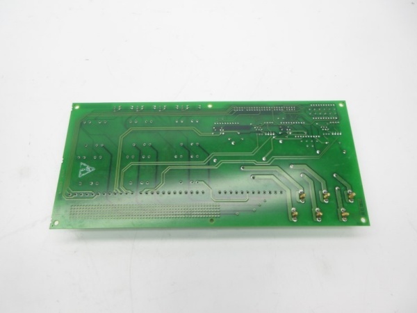
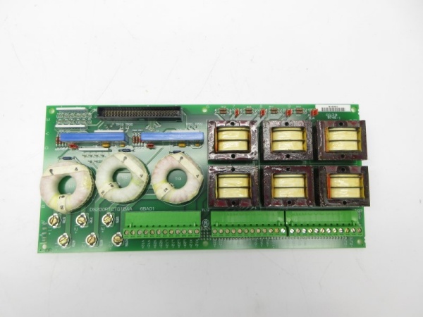
DS200PTCTG1BAA
The Real-World Problem It Solves
The Mark V control system requires an independent trip logic layer that can execute emergency shutdowns without relying on the main control processors (R, S, T). The DS200PTCTG1BAA (Turbine Trip Board – Revision BA) provides this critical safety function by monitoring protection signals, executing trip logic in the P-Core, and issuing physical relay outputs to trip fuel and steam valves. This board ensures that even if the main control system fails, emergency overspeed protection, manual trip commands, and external trip inputs can still initiate a turbine shutdown. The revision BA represents updated hardware with potential improvements in reliability, component substitutions, or functional enhancements while maintaining the same fundamental trip logic architecture.
Where you’ll typically find it:
- P-Core (Protective Core) rack – Location 9
- Gas turbine control systems with Mark V LM
- Steam turbine protection systems
- Any Mark V system requiring independent trip capability
- Applications with redundant protection requirements
- Systems upgraded with revision BA hardware
Bottom line: Independent trip logic executor for the P-Core, revision BA configuration—ensures emergency shutdown capability regardless of main control system status.
Hardware Architecture & Under-the-Hood Logic
The DS200PTCTG1BAA (Revision BA) is the trip logic processor for the P-Core protective module in Mark V systems. This board receives protection signals from the PTBA terminal board (overspeed pickups, external trips, manual trip), processes these inputs through independent trip logic, and issues relay outputs to trip fuel valves, steam valves, and other emergency systems. The revision BA design maintains the same trip logic architecture as earlier TCTG boards but may incorporate circuit improvements, updated relay components, or artwork modifications based on GE engineering changes. Key functions include emergency overspeed trip (130% or 110% depending on turbine configuration), generator breaker control (52GL trip/close), manual trip processing, and external trip input monitoring. The board interfaces with PTBA for signal inputs, TCEB for alarm functions, and field devices through multiple trip output relays.
Signal flow:
- Overspeed signals from PTBA (3 magnetic pickups) feed into TCTG for emergency overspeed detection
- External trip signals (e.g., vibration, temperature, auxiliary trips) route from PTBA to TCTG
- Manual trip button input connects to TCTG for operator-initiated shutdowns
- Generator breaker signals (52GL) interface with TCTG for breaker control
- Trip logic processing occurs independently of main control processors (R, S, T)
- Emergency overspeed trip activates at configured threshold (typically 130% for steam turbines, 110% for gas turbines)
- Trip outputs issued to fuel valve trip solenoids
- Trip outputs issued to steam valve trip circuits
- Generator breaker trip signal (52GL) issued through TCTG
- LED indicators display trip status and fault conditions
- Trip latching logic maintains trip state until reset
- Interface with TCEB for alarm and indication functions
- Power supplied from 125 V DC bus for trip output relays
- Board operates in P-Core with redundancy (trip logic duplicated in X, Y, Z processors)
- Revision BA may include updated relay components or circuit modifications
DS200PTCTG1BAA
Field Service Pitfalls: What Rookies Get Wrong
Assuming TCTG trip logic is same as main control processors causes protection confusionConfusing P-Core trip logic with R> control processor logic. I’ve seen technicians configuring trip parameters on TCTG the same way as on main control processors, causing improper trip behavior.
- Field Rule: Understand TCTG operates independently of main control processors. P-Core trip logic uses different setpoints, thresholds, and processing methods. Emergency overspeed trip on TCTG is independent of R> processor overspeed protection. Never assume TCTG and R> processors have identical logic—consult GEH-6152 manual for TCTG-specific configuration. Verify trip setpoints match turbine specifications before placing in service.
Forgetting to verify trip output relay operation causes protection failureNot testing trip output relays after installation. I’ve seen technicians replacing TCTG boards without verifying trip output functionality, discovering relay failures only during actual trip events.
- Field Rule: Always test trip output relays after TCTG installation. Use relay tester or multimeter to verify relay contacts open/close correctly. Test fuel valve trip outputs, steam valve trip outputs, and generator breaker trip outputs. Verify relay contact resistance is within specifications. Check relay coil voltage is correct (typically 125 V DC). Never assume relays work correctly—test each trip output circuit individually.
Mixing up emergency overspeed setpoints causes improper trip thresholdsConfiguring wrong overspeed trip thresholds. I’ve seen technicians setting emergency overspeed trip at 110% for steam turbines (should be 130%) or 130% for gas turbines (should be 110%), causing nuisance trips or delayed protection.
- Field Rule: Verify emergency overspeed trip setpoint matches turbine type. Gas turbines typically use 110% for emergency overspeed—steam turbines typically use 130%. Check configuration against turbine specifications and GE documentation. Confirm setpoint is properly configured in TCTG logic. Never guess at overspeed setpoint—wrong setting compromises safety or causes nuisance trips.
Improper generator breaker control wiring causes synchronization issuesIncorrect 52GL breaker signal connections. I’ve seen technicians wiring generator breaker signals incorrectly, causing breaker maloperation or failure to trip during fault conditions.
- Field Rule: Verify 52GL breaker signals match system configuration. Generator breaker trip/close signals must connect to correct TCTG outputs. Check polarity and contact type (NO/NC) for breaker control circuits. Verify breaker status feedback signals route properly. Test breaker operation with simulated trip/close commands before placing in service. Never assume breaker wiring is correct—verify all connections.
Neglecting external trip input polarity causes missed tripsReverse polarity on external trip inputs. I’ve seen technicians connecting external trip signals with wrong polarity, causing TCTG to miss critical trip commands from auxiliary protection systems.
- Field Rule: Verify external trip input polarity matches original configuration. External trip inputs are typically polarity-sensitive DC signals. Document which terminals are positive and negative for each trip input. Test external trip activation with known-good source after installation. Check that all external trip sources (vibration, temperature, auxiliary) connect properly. Never assume trip inputs are AC—verify DC polarity requirements.
Failing to reset trip latches after testing causes persistent trip stateNot resetting trip latches after maintenance testing. I’ve seen technicians performing trip tests but forgetting to reset trip latches, causing persistent trip state after maintenance completion.
- Field Rule: Always reset trip latches after trip testing. TCTG maintains latched trip state until manually reset. Use reset procedure specified in GEH-6152 manual. Verify all LED indicators return to normal state after reset. Confirm trip output relays return to normal position. Never place turbine in service with latched trip state—reset all latches first.
Skipping revision BA compatibility checks causes installation errorsInstalling revision BA without verifying compatibility. I’ve seen technicians replacing older TCTG revisions with revision BA boards without checking compatibility, leading to configuration errors or communication failures.
- Field Rule: Verify revision BA compatibility before installation. Revision BA may have different jumper positions, connector assignments, or component values. Compare original board revision with replacement board. Consult GEH-6152 manual for revision compatibility matrix. Check for any engineering change notices (ECNs) applying to revision BA. Document any configuration differences between revisions. Never assume all TCTG boards are interchangeable—verify compatibility first.
Overlooking manual trip button functionality causes operator confusionNot testing manual trip button after installation. I’ve seen technicians replacing TCTG boards but not verifying manual trip button operation, causing operators to discover manual trip failure during emergency conditions.
- Field Rule: Always test manual trip button after TCTG installation. Verify manual trip button connects to correct TCTG input. Test manual trip function and confirm trip outputs activate. Check that manual trip LED indicator activates properly. Ensure manual trip reset function works correctly. Never rely solely on automatic trip functions—verify manual trip works too.
Commercial Availability & Pricing Note
Please note: The listed price is for reference only and is not binding. Final pricing and terms are subject to negotiation based on current market conditions and availability.


