
Description
Hard-Numbers: Technical Specifications
- Functional Acronym: PTBA
- Group Number: G1
- Revision: BA (Board Revision B, Artwork Revision A)
- Core Location: P-Core (Protective Core) – Location 6
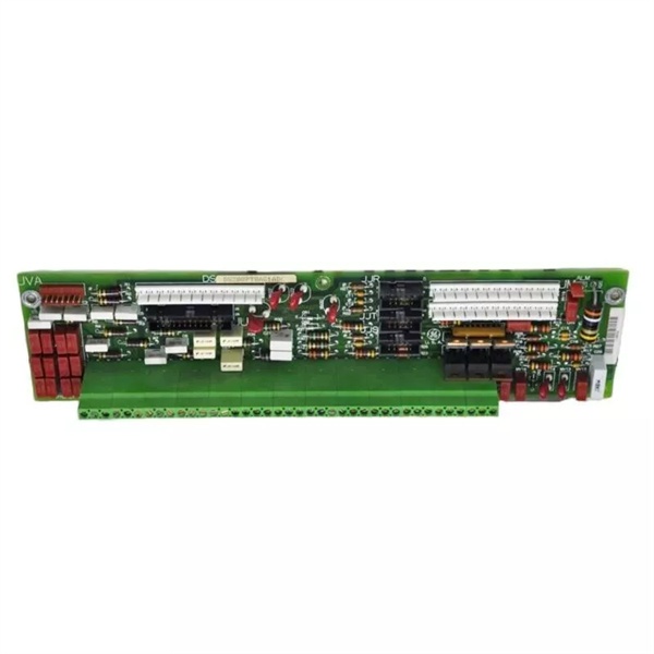
- Terminal Blocks: 2 blocks (TB1, TB2) with 72 terminals each = 144 total signal wire terminations
- Connectors: 3 x 10-pin connectors (JJR, JJT, JJS) + 6 terminal posts for additional signal wires
- Dimensions: 3 inches H × 11.5 inches W × 7.2 cm D (28.8 cm × 7.2 cm × 3.8 cm)
- Weight: 0.32 kg (0.7 lbs)
- PCB Coating: Normal coating (non-conformal)
- Manual: GEH-6153 (Protective Terminal Board Manual)
- Hardware Jumper: J1 (horn enable/disable)
- Power Distribution: JVA distributes 335 V DC to flame detection devices
- Interfaced Boards: TCEB (Core Extender Board), TCTG (Turbine Trip Board), TCQE (Quadruple Extender Board)
The Real-World Problem It Solves
The Mark V control system requires a centralized termination point for all critical protection signals that feed into the independent protection module (P-Core). The DS200PTBAG1ABA (revision BA) provides this interface, ensuring that overspeed protection, flame detection, generator synchronization signals, and external trip inputs are properly conditioned and routed to the protective processors (X, Y, Z). This revision represents a board-level update that may include artwork changes, component substitutions, or functional improvements over earlier revisions while maintaining backward compatibility with the Mark V P-Core architecture.
Where you’ll typically find it:
- Gas turbine control systems with Mark V LM
- Steam turbine protection systems
- P-Core (protective core) rack – Location 6
- Any Mark V system requiring independent protection module
- Applications with redundant overspeed protection requirements
- Systems retrofitted with revision BA hardware updates
Bottom line: Critical signal termination interface for the independent protection module, revision BA configuration—ensuring redundant safety systems receive accurate field signals.

DS200PTBAG1A
Hardware Architecture & Under-the-Hood Logic
The DS200PTBAG1ABA (Revision BA) serves as the field device interface for the P-Core protection module in Mark V systems. This revision maintains the same fundamental architecture as earlier PTBA boards but may incorporate circuit modifications, updated components, or artwork improvements based on GE engineering change orders. The board handles three magnetic speed pickup inputs for redundant overspeed protection, distributes high voltage (335 V DC) to flame detection devices via JVA, and provides termination points for generator PT/CT voltage and current signals. The J1 hardware jumper controls the audible alarm (horn) power from the TCEB board. Signal routing follows the standard connector assignments: JJR for shaft speed signals to TCQE, JM for emergency trip signals to TCTG, JN for external trip signals, JU for overspeed and flame detection signals to TCEB, JV for generator/bus voltage signals to TCEB, and JVA for flame detector power distribution.
Signal flow:
- Field devices connect to terminal blocks TB1 and TB2 (144 total terminations)
- Magnetic speed pickups (3 units) terminate for overspeed protection
- Flame detector signals route through JVA (335 V DC distribution from TCEB)
- Generator PT and CT signals terminate on voltage/current inputs
- External trip signals terminate and route to TCTG via JN connector
- Emergency trip outputs read/write via JM connector to TCTG
- Shaft speed signals (high/low pressure) route via JJR to TCQE
- Generator/breaker signals (52GL, G125P) route via JM and JN
- Overspeed and flame detection signals route via JU to TCEB
- Generator/bus voltage and current signals route via JV to TCEB
- Horn enable/disable controlled by J1 hardware jumper
- JJS/T connector typically unused (vestigial)
- No active signal processing—pure termination and routing function
- Protective processors X, Y, Z in P-Core receive signals via this board
- Independent protection path separate from main control processors
Field Service Pitfalls: What Rookies Get Wrong
Assuming revision compatibility without verification causes retrofit failuresInstalling revision BA without checking system compatibility. I’ve seen technicians replacing older PTBA revisions with revision BA boards without verifying compatibility, leading to communication errors with other P-Core boards.
- Field Rule: Always verify revision compatibility before installation. Revision BA may have different jumper positions, connector pinouts, or component values. Compare original board revision with replacement board. Consult GEH-6153 manual for revision compatibility matrix. Check if any engineering change notices (ECNs) apply to revision BA. Document any configuration differences between revisions. Never assume all PTBA boards are interchangeable—verify compatibility first.
Incorrect documentation during board swap causes configuration lossFailing to document original jumper and connector positions. I’ve seen technicians replacing boards without documenting the original configuration, then struggling to restore proper settings on the new board.
- Field Rule: Document original board configuration completely before removal. Photograph the entire board, including jumper positions, connector labels, and terminal wiring. Record all jumper settings (especially J1 for horn enable). Note any field modifications or unusual connections. Create a terminal map for TB1 and TB2 connections. Compare new board configuration with original before installation. Never rely on memory—document everything visible on the original board.
Forgetting to transfer custom wire modifications causes functional gapsMissing custom wiring adaptations. I’ve seen technicians overlooking field-installed modifications (like added jumpers or relocated wires) when replacing boards, causing lost functionality.
- Field Rule: Identify all field modifications before board removal. Look for added jumpers, relocated wires, or terminal changes. Document any non-standard wiring that may exist on the original board. Transfer identical modifications to the replacement board. Verify modified connections are properly secured. Check that custom adaptations still function with revision BA components. Never assume factory configuration is the only configuration—field modifications exist.
Neglecting to verify flame detector power on revision BA causes false alarmsOverlooking JVA voltage differences in revision BA. I’ve seen technicians not verifying flame detector power output after revision BA installation, causing flame detection circuits to malfunction.
- Field Rule: Verify JVA 335 V DC output on revision BA after installation. Measure JVA terminal voltage with multimeter before connecting flame detectors. Confirm voltage matches system specifications (typically 335 V DC). Check polarity on all JVA connections—revision BA may have different terminal assignments. Test flame detector operation before placing turbine in service. Never assume flame detector power is identical across revisions—verify actual output.
Mixing up terminal block assignments causes signal routing errorsConfusing TB1 and TB2 signal assignments. I’ve seen technicians not distinguishing between the two 72-terminal blocks, resulting in mixed signal routing and protection faults.
- Field Rule: Distinguish TB1 from TB2 signal assignments. These blocks may serve different signal groups (e.g., TB1 for inputs, TB2 for outputs). Document which block carries which signal types. Label terminal blocks clearly before wire removal. Verify terminal assignments match original configuration after installation. Never mix TB1 and TB2 wires—each block has dedicated signal routing paths.
Improper connector mating on revision BA causes intermittent signalsIncorrect connector insertion on revision BA. I’ve seen technicians forcing connectors into revision BA ports, causing bent pins and intermittent signals.
- Field Rule: Verify connectors mate smoothly with revision BA sockets. Check for connector keying—revision BA may have different keying positions. Inspect connector pins for damage before insertion. Ensure connectors are fully seated and locked. Test signal continuity after connector mating. Never force a misaligned connector—revision BA may have updated connector geometry.
Skipping signal verification after revision BA installation causes latent faultsNot testing all signals after board replacement. I’ve seen technicians installing revision BA boards without comprehensive signal testing, discovering issues only during turbine startup.
- Field Rule: Perform complete signal verification after revision BA installation. Test overspeed pickup signals with signal generator or simulated input. Verify flame detector power and signal paths. Check generator PT/CT voltage and current readings. Test external trip circuit functionality. Verify all protective processor inputs receive correct signals. Use Mark V diagnostic tools to confirm signal integrity. Never assume revision BA works without verification—test all signal paths.
Failing to update maintenance records with revision BA information causes confusionNot documenting board revision in maintenance logs. I’ve seen technicians not updating records after revision BA installation, leading to confusion during future maintenance.
- Field Rule: Update all maintenance records with revision BA information. Document board revision, installation date, and configuration settings. Note any compatibility issues encountered during installation. Store photographs of original and new board configurations. Update spare parts inventory with revision BA details. Never leave maintenance records outdated—future service depends on accurate documentation.
Commercial Availability & Pricing Note
Please note: The listed price is for reference only and is not binding. Final pricing and terms are subject to negotiation based on current market conditions and availability.


