
Description
Hard-Numbers: Technical Specifications
- Functional Acronym: PTBA
- Group Number: G1
- Core Location: P-Core (Protective Core) – Location 6
- Terminal Blocks: 2 blocks (TB1, TB2) with 72 terminals each = 144 total signal wire terminations
- Connectors: 3 x 10-pin connectors (JJR, JJT, JJS) + 6 terminal posts for additional signal wires
- Dimensions: 3 inches H × 11.5 inches W × 7.2 cm D (28.8 cm × 7.2 cm × 3.8 cm)
- Weight: 0.32 kg (0.7 lbs)
- PCB Coating: Normal coating (non-conformal)
- Manual: GEH-6153 (Protective Terminal Board Manual)
- Hardware Jumper: J1 (horn enable/disable)
- Power Distribution: JVA distributes 335 V DC to flame detection devices
- Interfaced Boards: TCEB (Core Extender Board), TCTG (Turbine Trip Board), TCQE (Quadruple Extender Board)
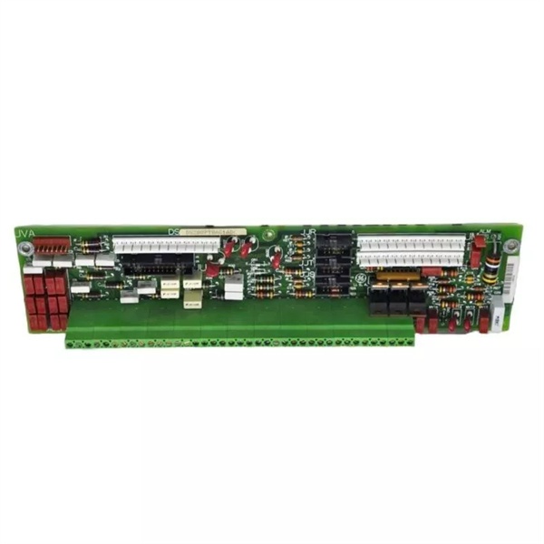
DS200PTBAG1A
The Real-World Problem It Solves
The Mark V control system requires a centralized termination point for all critical protection signals that feed into the independent protection module (P-Core). The DS200PTBAG1A provides this interface, ensuring that overspeed protection, flame detection, generator synchronization signals, and external trip inputs are properly conditioned and routed to the protective processors (X, Y, Z). Without this board, the redundant protection layer that operates independently from the main control processors would have no reliable connection to field devices, compromising system safety.
Where you’ll typically find it:
- Gas turbine control systems with Mark V LM
- Steam turbine protection systems
- P-Core (protective core) rack – Location 6
- Any Mark V system requiring independent protection module
- Applications with redundant overspeed protection requirements
Bottom line: Critical signal termination interface for the independent protection module, ensuring redundant safety systems receive accurate field signals.
Hardware Architecture & Under-the-Hood Logic
The DS200PTBAG1A serves as the field device interface for the P-Core protection module in Mark V systems. This terminal board does not process signals—it terminates, conditions, and routes them to the appropriate protection processor boards. The board handles both primary and emergency overspeed protection through three magnetic speed pickup inputs, distributes high voltage (335 V DC) to flame detection devices via JVA, and provides termination points for generator PT/CT voltage and current signals. The J1 hardware jumper controls the audible alarm (horn) power from the TCEB board. Signal routing is handled through multiple connectors: JJR for shaft speed signals to TCQE, JM for emergency trip signals to TCTG, JN for external trip signals, JU for overspeed and flame detection signals to TCEB, JV for generator/bus voltage signals to TCEB, and JVA for flame detector power distribution.
Signal flow:
- Field devices connect to terminal blocks TB1 and TB2 (144 total terminations)
- Magnetic speed pickups (3 units) terminate for overspeed protection
- Flame detector signals route through JVA (335 V DC distribution from TCEB)
- Generator PT and CT signals terminate on voltage/current inputs
- External trip signals terminate and route to TCTG via JN connector
- Emergency trip outputs read/write via JM connector to TCTG
- Shaft speed signals (high/low pressure) route via JJR to TCQE
- Generator/breaker signals (52GL, G125P) route via JM and JN
- Overspeed and flame detection signals route via JU to TCEB
- Generator/bus voltage and current signals route via JV to TCEB
- Horn enable/disable controlled by J1 hardware jumper
- JJS/T connector typically unused (vestigial)
- No active signal processing—pure termination and routing function
- Protective processors X, Y, Z in P-Core receive signals via this board
- Independent protection path separate from main control processors
Field Service Pitfalls: What Rookies Get Wrong
Failing to document terminal connections causes extended downtimeNot mapping wire positions before removal. I’ve seen technicians pulling all 144 signal wires without marking terminal IDs, then spending hours tracing connections during replacement.
- Field Rule: Always document terminal positions before removal. Use terminal IDs (e.g., TB1 27, TB2 70) to mark each wire connection. Photograph the board with all wires attached. Create tags for each terminal connection. Never rely on memory—this board has too many connections. Map out both terminal blocks (TB1 and TB2) and all 72 terminals per block. Document connector positions (JJR, JJT, JJS, JM, JN, JU, JV, JVA) with wire routing.
Confusing connector functions causes misrouted signalsMixing up connector signal assignments. I’ve seen technicians connecting JJR signals to JM or JN connectors, causing speed signals to route to trip functions instead of processor inputs.
- Field Rule: Memorize connector functions: JJR = speed to TCQE, JM = emergency trip to TCTG, JN = external trip to TCTG, JU = overspeed/flame to TCEB, JV = voltage/current to TCEB, JVA = flame detector power (335 V DC). Never assume connectors are interchangeable—each has a specific routing path. Verify connector labels on the board match cable markings. Document which ribbon cable connects to which connector before removal.
Magnetic pickup phasing errors cause false overspeed tripsImproper pickup wiring sequence. I’ve seen technicians connecting the three magnetic speed pickups in wrong phase sequence, causing the protection processors to interpret phase differences as overspeed conditions.
- Field Rule: Verify magnetic pickup phasing matches original configuration. The three pickups must maintain proper phase relationship for accurate overspeed detection. Document which pickup connects to which terminal before removal. Test pickup output signals with oscilloscope after installation if available. Never swap pickup wires without verifying system configuration—this can cause nuisance trips.
Forgetting J1 jumper causes unwanted horn activationLeaving horn enable jumper installed during maintenance. I’ve seen technicians replacing the board but forgetting to remove the J1 jumper, causing the horn to activate continuously during testing.
- Field Rule: J1 jumper controls horn enable—remove to silence. Document original J1 position before removal. If horn was disabled, ensure J1 is removed on replacement board. If horn was enabled, ensure J1 is installed. Never assume J1 position—verify original configuration. Test horn function after installation to confirm proper operation.
Mishandling 335 V DC flame detector power causes safety hazardsImproper JVA connection procedures. I’ve seen technicians servicing JVA connections without proper de-energization, exposing themselves to hazardous voltage levels.
- Field Rule: JVA distributes 335 V DC from TCEB to flame detectors—treat as hazardous. Always verify power is de-energized before servicing JVA connections. Use insulated tools when working with JVA terminals. Never touch JVA terminals while system is powered. Verify flame detector power is off before disconnecting devices. Follow lockout/tagout procedures for high-voltage DC circuits.
PT/CT wiring errors cause protection malfunctionIncorrect generator voltage/current connections. I’ve seen technicians swapping PT (potential transformer) and CT (current transformer) connections, causing voltage signals to feed into current circuits and vice versa.
- Field Rule: Verify PT and CT connections match terminal IDs. PT connections are for voltage sensing—CT connections are for current sensing. Never interchange PT and CT terminations—this damages protection circuits. Document which terminals connect to PTs and which connect to CTs. Verify instrument transformer ratios match system configuration after installation. Test PT/CT signals with appropriate meters before energizing.
Ignoring external trip signal polarity causes protection failureReverse polarity on trip input connections. I’ve seen technicians connecting external trip signals with wrong polarity, causing the protection processors to miss critical trip commands.
- Field Rule: Verify external trip signal polarity matches original configuration. External trip inputs are polarity-sensitive—reverse wiring prevents trip detection. Document which terminal is positive and which is negative for each trip input. Test trip signal activation with known-good source after installation. Never assume trip signals are AC—most are DC with specific polarity requirements.
Overshadowing emergency vs primary overspeed protection causes configuration errorsConfusing protection processor responsibilities. I’ve seen technicians configuring emergency overspeed settings on primary protection processors or vice versa, compromising redundant protection layers.
- Field Rule: Understand dual-level overspeed protection. Primary overspeed uses R> control processor with BBL blocks—emergency overspeed uses P-Core processors X, Y, Z. These are independent protection paths. Don’t configure one in place of the other. Magnetic pickups on PTBA feed both protection levels. Verify both primary and emergency overspeed setpoints are configured independently. Never assume primary protection covers emergency protection—both must be functional.
Commercial Availability & Pricing Note
Please note: The listed price is for reference only and is not binding. Final pricing and terms are subject to negotiation based on current market conditions and availability.


