
Description
Key Technical Specifications
-
Model Number: DS200PCCAG9A
-
Manufacturer: General Electric (GE)
-
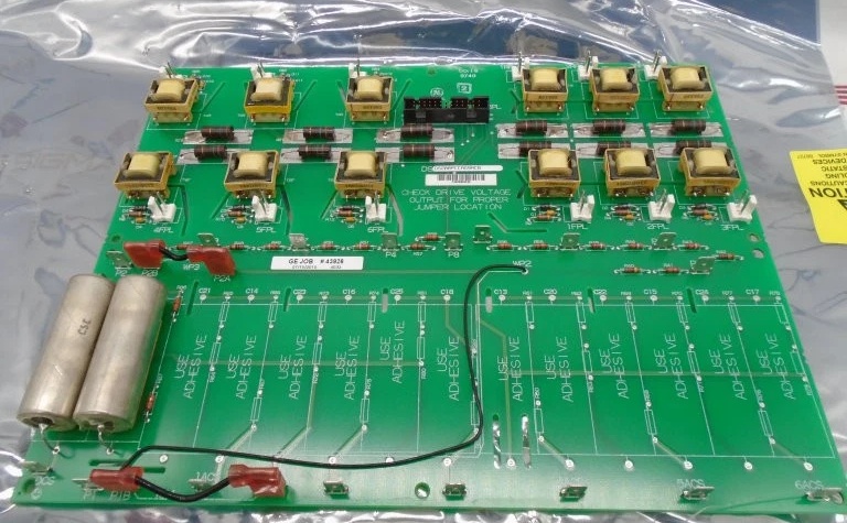
Functional Description: Power-connect card (PCCA) – armature voltage scaling, snubber bus, bridge feedback
-
Armature Voltage Range: 240-630 V regenerative (jumper-selected scaling)
-
Logic Supply: +5 Vdc @ 6 A (from drive back-plane)
-
Jumpers: 17 positions for voltage class, CT ratio, snubber RC values
-
Isolation: 3750 V basic insulation channel-to-ground
-
Connectors: 8 screw terminals (E1-E8), 96-pin DIN 41612 to VME back-plane
-
PCB Coating: Normal thickness, anti-static / moisture barrier
-
Operating Temperature: –40 °C…+70 °C
-
Dimensions / Weight: 159 × 178 × 50 mm, 0.8 kg; rack mount
-
Manual: GEI-100161 (PCCA Power Connect Card Manual)

GE DS200PCCAG9A
Field Application & Problem Solved
EX2000 / EX2100 drives need a card that sits between the low-voltage DSP board and the 600 V SCR bridge—scaling the DC link voltage down to 0-10 V, distributing snubber RC networks, and carrying the armature current feedback. Plug the DS200PCCAG1A into the Mark V rack: jumper-select 480 V class, land the bus bars on E1-E4, and the on-board divider gives the DSP a safe 10 V replica. I’ve used these on 7FA peakers—one card per bridge, hot-swappable while the unit is on turning gear, and you still meet UL isolation without external hardware. Value: it collapses voltage divider, snubber bus, and CT buffer into one 0.8 kg card you can swap in two minutes.
EX2000 / EX2100 drives need a card that sits between the low-voltage DSP board and the 600 V SCR bridge—scaling the DC link voltage down to 0-10 V, distributing snubber RC networks, and carrying the armature current feedback. Plug the DS200PCCAG1A into the Mark V rack: jumper-select 480 V class, land the bus bars on E1-E4, and the on-board divider gives the DSP a safe 10 V replica. I’ve used these on 7FA peakers—one card per bridge, hot-swappable while the unit is on turning gear, and you still meet UL isolation without external hardware. Value: it collapses voltage divider, snubber bus, and CT buffer into one 0.8 kg card you can swap in two minutes.
Installation & Maintenance Pitfalls (Expert Tips)
Bus bars float at bridge potential—short them last – If you land the DC link lugs while the bus is hot you’ll arc-weld the 3750 V isolator. De-energize, wait for bus < 50 V, then torque lugs to 0.8 Nm or vibration will walk them out.
Jumper map is silk-screened backwards – JP1-17 numbers read from the component side; if you mirror the board you’ll set 600 V attenuation on a 240 V system and wonder why the DSP sees 200 % over-voltage. Use the drawing, not eye-balling.
Snubber caps hold charge after DC bus is down – The 2 µF film bank sits at bridge potential; if you pull the card before the bus bleeds you’ll arc-weld the connector pins. Wait for the DC link < 50 V or use the external discharge resistor.
5 V @ 6 A must come from the back-plane – If you power the card from an external supply you’ll back-feed the VME bus and blow the 5 A polyfuse. Verify the back-plane fuse is good before you insert the card.
GE DS200PCCAG9A
Technical Deep Dive & Overview
Internally the DS200PCCAG9A is a passive divider network bolted to an analog buffer. The divider chain drops 630 V bus to 10 V with 0.1 %, 25 ppm resistors; the buffer feeds the DSP via an isolation amplifier with < 1 µs delay. A separate path handles snubber RC—jumper-selectable 0.47-2 µF per phase, low-inductance film, giving < 50 ns dv/dt clamping. No firmware—pure analog signal chain—so you can swap it without reloading the controller .
Internally the DS200PCCAG9A is a passive divider network bolted to an analog buffer. The divider chain drops 630 V bus to 10 V with 0.1 %, 25 ppm resistors; the buffer feeds the DSP via an isolation amplifier with < 1 µs delay. A separate path handles snubber RC—jumper-selectable 0.47-2 µF per phase, low-inductance film, giving < 50 ns dv/dt clamping. No firmware—pure analog signal chain—so you can swap it without reloading the controller .


