
Description
Hard-Numbers: Technical Specifications
- Functional Acronym: PCCA
- Group Number: G7
- Power Classification: Low-horsepower controller (both AC and DC snubbers)
- Snubber Configuration: Both AC and DC snubbers (onboard)
- Fuse Type: Line fuses and reactors (not leg fuses)
- Frame Compatibility: C and G style frames
- Power Supply Board: SDCI-compatible (G7, G8, G9, G10 all use SDCI)
- Bus Transformer: Separate or common bus transformer support
- Configuration Jumpers: 4 wire jumpers (JP1, JP2, WP3, WP4)
- Connectors: Gate pulse connectors + power supply communication (5PL)
- AC Voltage Rating: <600 V rms maximum
- PCB Coating: Normal coating (non-conformal)
- Manual: GEI-100161 (PCCA Power Connect Card Manual)
- Revisions: Functional Revision 1 (A), Functional Revision 2 (C), Artwork Revision (B)

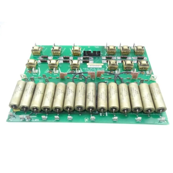
GE DS200PCCAG7ACB
The Real-World Problem It Solves
Industrial drives operating under 600V RMS require a power interface card that integrates voltage protection directly on the board through snubber circuits, eliminating the need for external snubber networks. The DS200PCCAG7ACB provides complete onboard AC and DC snubber protection with line fuses for overcurrent protection, making it ideal for lower-power applications where compact design and integrated protection are priorities. Its C/G frame compatibility and SDCI power supply integration simplify installation in standard drive configurations.
Where you’ll typically find it:
- Industrial motor drives under 600V
- Pump and fan applications
- Conveyor systems
- Low-horsepower turbine controls
- Standard Mark V drive cabinets with C or G frames
Bottom line: Integrated protection solution for low-power SCR gate control applications requiring onboard snubber circuits.
Hardware Architecture & Under-the-Hood Logic
The DS200PCCAG7ACB serves as the interface between the drive control circuitry and the SCR power bridge in lower-power applications. As a Group 7 PCCA, it features both AC and DC snubber circuits directly on the board—unlike G5/G6 boards that rely on external snubbers. The board uses line fuses (not leg fuses) for protection and communicates with the SDCI power supply board through dedicated connectors. Four configurable jumpers (JP1, JP2, WP3, WP4) allow for system-specific adjustments to voltage settings and signal routing. The board is designed for C and G style frames and lacks onboard diagnostic components like LEDs or test points, relying on system-level monitoring for fault detection.
Signal flow:
- Gate drive control signals received from drive control board
- Signals routed through pulse transformers for galvanic isolation
- Isolated gate pulses transmitted via gate connectors to SCR bridge
- Onboard AC snubber circuits suppress AC voltage transients
- Onboard DC snubber circuits suppress DC voltage transients
- Line fuses provide overcurrent protection (not leg fuses)
- Power supply communication handled through 5PL connector to SDCI power supply board
- Jumpers JP1 and JP2 configure voltage connections to stab terminals P3-P10
- Jumpers WP3 and WP4 conjoin P2A to P2B and P1A to P1B for signal routing
- Voltage feedback signals monitored for bridge status
- No onboard LEDs, test points, or switches—fault detection through system-level monitoring
- Board mounted in C or G style frame configurations
GE DS200PCCAG7ACB
Field Service Pitfalls: What Rookies Get Wrong
Confusing line fuses with leg fuses causes protection failuresWrong fuse replacement type. I’ve seen technicians replacing blown line fuses with leg fuses, compromising the protection scheme specifically designed for G7 low-power applications.
- Field Rule: G7 boards use line fuses (not leg fuses). G1, G2, G7, and G8 groups have line fuses while G5, G6, G9, and G10 use leg fuses. Verify the exact fuse rating and type for each line fuse position. Never substitute leg fuses for line fuses—the protection characteristics differ significantly. Document all line fuse ratings during installation. Check line fuses individually after any overcurrent event.
Assuming external snubbers are required causes wiring errorsLooking for nonexistent external snubber connections. I’ve seen technicians attempting to connect external snubber circuits to G7 boards, not realizing this board has complete onboard AC and DC snubber protection.
- Field Rule: G7 boards have both AC and DC snubbers directly onboard—this is by design. Never attempt to connect external snubber circuits to a G7 board. The onboard snubber network handles all voltage transient suppression for low-power applications. Verify snubber components are intact on the board during installation. Don’t waste time looking for external snubber connections that don’t exist.
Ignoring SDCI power supply compatibility causes communication faultsUsing incorrect power supply boards. I’ve seen technicians connecting G7 boards to non-SDCI power supply boards, causing communication failures and drive shutdowns.
- Field Rule: G7 boards require SDCI power supply boards. G7, G8, G9, and G10 groups all use SDCI power supply boards. Verify the power supply board part number matches system requirements. Check the 5PL connector pinout for proper communication signals. Never mix incompatible power supply board types with different PCCA groups.
Misconfiguring JP1/JP2 jumpers for C/G frames causes voltage mismatchIncorrect jumper connections for stab terminals. I’ve seen technicians connecting JP1 and JP2 jumpers to wrong stab terminals, resulting in improper voltage scaling and drive faults.
- Field Rule: JP1 and JP2 jumpers must connect to appropriate stab terminals in locations P3-P10. These include stabs P1, P1A, P1B, P2, P2A, P2B, P3-P10, DCS, and 1ACS-6ACS. Photograph the original jumper positions before removal and replicate them exactly. Never assume default jumper settings match your C or G frame configuration. Consult GEI-100161 for exact jumper terminal assignments.
Forgetting WP3/WP4 jumper function causes signal routing errorsMissing P2A/P2B and P1A/P1B connections. I’ve seen technicians leaving WP3 and WP4 jumpers disconnected or incorrectly placed, resulting in incomplete signal paths.
- Field Rule: WP3 conjoins P2A to P2B, and WP4 conjoins P1A to P1B. These connections are critical for proper signal routing on G7 boards. Verify both WP3 and WP4 are correctly installed in their designated positions. Check continuity across these jumper connections after installation. Never operate a G7 board with missing or improperly configured WP3/WP4 jumpers.
Overlooking C/G frame compatibility causes installation failuresWrong frame selection. I’ve seen technicians attempting to install G7 boards in non-C or non-G frames, not realizing G7 is designed specifically for C and G style frames only.
- Field Rule: Verify frame compatibility before installation. G7 boards are designed for C and G style frames only. Check the existing frame designation on the drive cabinet. Never attempt to force-fit G7 boards into other frame types. Confirm frame style matches the board’s intended application. J/K/M frames require different PCCA groups.
Missing line reactor connections causes current imbalanceLoose or missing line reactor connections. I’ve seen technicians failing to properly secure line reactor connections, leading to current imbalance and premature fuse failure.
- Field Rule: Ensure all line reactor connections are tight and properly torqued. Use a torque wrench set to manufacturer specifications. Inspect reactor connections for corrosion or damage during board replacement. Perform a resistance check across each reactor to verify integrity. Never operate the drive with loose reactor connections. Line reactors work with line fuses for proper protection.
Assuming G7 is interchangeable with other groups causes system damageWrong group substitution. I’ve seen technicians replacing G7 boards with G5 or G6 boards, resulting in incompatible snubber configurations and fuse types.
- Field Rule: Group 7 boards have unique characteristics (onboard AC and DC snubbers, line fuses, C/G frame compatibility) that make them incompatible with other groups. Always replace G7 boards with exact same group. Check the full part number including the “G7” designation. Never assume physical similarity means functional compatibility. The presence of onboard snubbers distinguishes G7 from high-power groups.
Neglecting torque specifications causes intermittent connectionsImproper mounting torque. I’ve seen technicians failing to follow proper torque specifications when securing board mounting hardware, resulting in intermittent connections and random drive faults.
- Field Rule: Follow torque tightening specifications labeled on the drive for all mounting hardware. Use a torque screwdriver to secure connections to specification. Check all mounting points after installation. Never rely on hand-tightening alone, as vibration can loosen connections over time. Verify torque specifications match the frame type (C or G).
Commercial Availability & Pricing Note
Please note: The listed price is for reference only and is not binding. Final pricing and terms are subject to negotiation based on current market conditions and availability.


