
Description
Key Technical Specifications
-
Model Number: DS200PCCAG6A
-
Manufacturer: General Electric (GE)
-
Voltage Class: 240-630 VAC regenerative (jumper-selected)
-
Isolation: 2 kV basic input-to-logic; pulse-transformer gate drive
-
Jumpers: 17 positions for voltage class, CT ratio, snubber RC values
-
Current Interface: 0-5 A CT secondary, 10:1 or 1:1 jumper-selectable
-
Power Supply: +5 V & ±15 V from back-plane; field loops self-powered
-
Connectors: 96-pin DIN 41612 to VME rack; screw terminals for shunt & CT inputs
-
Operating Temperature: –40 °C…+70 °C
-
Dimensions / Weight: 159 × 178 mm, 0.7 lb (0.32 kg)
-
Protection Degree: IP20 rack-mount
-
Manual: GEI-100161 (PCCA Power Connect Card Manual)

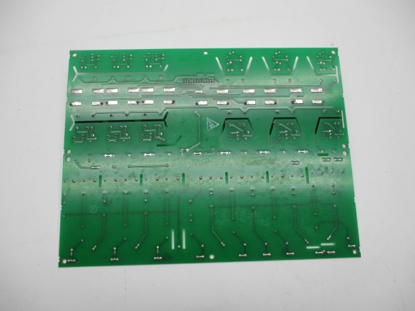
DS200PCCAG6A
Field Application & Problem Solved
In the field the biggest headache is getting the 480 V SCR bridge to talk to the 5 V DSP without blowing up the back-plane. The board solves that by living between the bridge and the Mark V rack—scaling 630 V bus down to 10 V, isolating the 5 A CT secondaries, and firing the SCRs through pulse transformers. You’ll typically find one card per six-pulse bridge on 7EA peakers—swap it while the unit is on turning gear and you still meet UL isolation without external hardware. Core value: it collapses a high-voltage divider, CT buffer, snubber network, and pulse transformer driver into one plug-in card you can carry in your shirt pocket.
In the field the biggest headache is getting the 480 V SCR bridge to talk to the 5 V DSP without blowing up the back-plane. The board solves that by living between the bridge and the Mark V rack—scaling 630 V bus down to 10 V, isolating the 5 A CT secondaries, and firing the SCRs through pulse transformers. You’ll typically find one card per six-pulse bridge on 7EA peakers—swap it while the unit is on turning gear and you still meet UL isolation without external hardware. Core value: it collapses a high-voltage divider, CT buffer, snubber network, and pulse transformer driver into one plug-in card you can carry in your shirt pocket.
Installation & Maintenance Pitfalls (Expert Tips)
Bus Bars Float at Bridge Potential—Short Them Last
The DC link lugs sit at 480-630 V. If you land the wires while the bus is hot you’ll arc-weld the 2 kV isolator. De-energize, wait for bus < 50 V, then torque lugs to 0.8 Nm or vibration will walk them out
The DC link lugs sit at 480-630 V. If you land the wires while the bus is hot you’ll arc-weld the 2 kV isolator. De-energize, wait for bus < 50 V, then torque lugs to 0.8 Nm or vibration will walk them out
.
Jumper Map Reads from Component Side
JP1-17 numbers look backwards if you flip the card. Set 600 V on a 480 V system and the DSP sees 125 % over-voltage, trips on “Over-Volt” every load swing. Use the drawing, not eye-balling
JP1-17 numbers look backwards if you flip the card. Set 600 V on a 480 V system and the DSP sees 125 % over-voltage, trips on “Over-Volt” every load swing. Use the drawing, not eye-balling
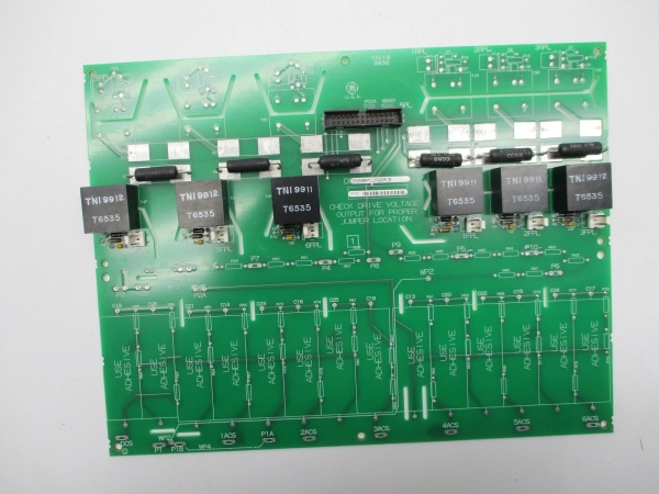
DS200PCCAG6A
.
CT Secondaries Must Be Shorted Before Disconnect
The 10:1 attenuator looks like 1.5 Ω to the CT. Open-circuit it and you’ll see 2 kV spikes that blow the input resistors. Use the supplied shorting blocks—never trust the CT shorting switch alone.
The 10:1 attenuator looks like 1.5 Ω to the CT. Open-circuit it and you’ll see 2 kV spikes that blow the input resistors. Use the supplied shorting blocks—never trust the CT shorting switch alone.
Snubber Caps Hold Charge After Bus Is Down
The 2 µF film bank sits at bridge potential. If you pull the card before the bus bleeds you’ll arc-weld the connector pins. Wait for DC link < 50 V or use the external discharge resistor
The 2 µF film bank sits at bridge potential. If you pull the card before the bus bleeds you’ll arc-weld the connector pins. Wait for DC link < 50 V or use the external discharge resistor
.
Technical Deep Dive & Overview
Internally the card is a passive divider network bolted to a pulse-transformer array. The divider chain drops 630 V to 10 V with 0.1 % resistors; the pulse transformers generate the 15 V gate pulses while keeping the 600 V bridge floating. All tuning lives in jumpers—no firmware—so you can swap it without reloading parameters; just remember to re-check the jumper map or the bridge will either under-fire or over-volt on the first pulse.
Internally the card is a passive divider network bolted to a pulse-transformer array. The divider chain drops 630 V to 10 V with 0.1 % resistors; the pulse transformers generate the 15 V gate pulses while keeping the 600 V bridge floating. All tuning lives in jumpers—no firmware—so you can swap it without reloading parameters; just remember to re-check the jumper map or the bridge will either under-fire or over-volt on the first pulse.


