
Description
Hard-Numbers: Technical Specifications
- Functional Acronym: PCCA
- Group Number: G5
- Power Conversion Type: High-horsepower controller
- Snubber Configuration: No onboard snubbers (eliminated—snubbers located elsewhere in system)
- Attenuation String: No attenuation string (eliminated)
- Fuse Type: Leg fuses (not line fuses—G5/G6/G9/G10 use leg fuses)
- Frame Compatibility: J, K, and M style frames
- Power Supply Board: DCFB compatible
- Bus Transformer: Separate or common bus transformer support
- Configuration Jumpers: 4 wire jumpers (JP1, JP2, WP3, WP4)
- Connectors: 12 plug connectors for gate pulses (forward and reverse) + 1 for power supply communication
- Mounting: 6 plastic holders securing board to board carrier
- PCB Coating: Normal coating (non-conformal)
- Manual: GEI-100161 (PCCA Power Connect Card Manual)
- Revisions: Functional Revision A, Functional Revision 2 (C), Artwork Revision B

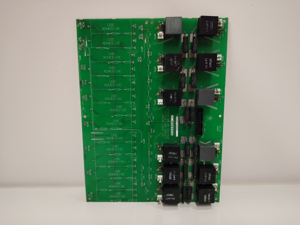
GE DS200PCCAG5ACB
The Real-World Problem It Solves
High-horsepower drive systems require specialized power interfaces where snubber circuits are relocated from the PCCA board to handle higher power levels. The DS200PCCAG5ACB provides the critical gate drive signal isolation and distribution for applications exceeding standard power ranges, where centralized snubber circuits would be inadequate. Its G5 group classification indicates this high-power architecture with leg fuse protection and frame-specific compatibility.
Where you’ll typically find it:
- High-horsepower motor drives in heavy industry
- Large pump and fan applications
- High-power turbine control systems
- Industrial drives requiring J/K/M frame configurations
Bottom line: High-horsepower power interface for SCR gate control in applications requiring external snubber circuits.
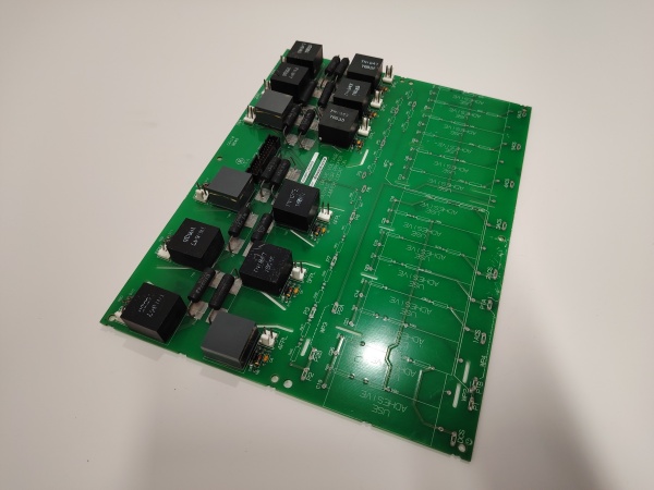
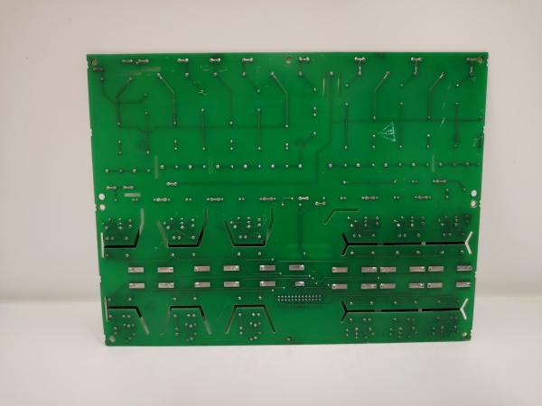
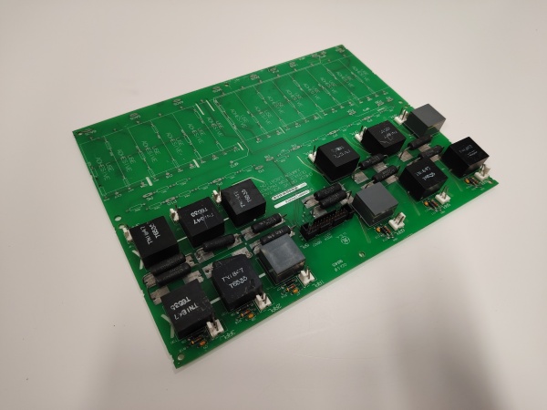
Hardware Architecture & Under-the-Hood Logic
The DS200PCCAG5ACB serves as the interface between the drive control circuitry and the SCR power bridge, transmitting gate drive pulses through pulse transformers for isolation. This Group 5 variant is designed for high-horsepower applications with no onboard snubber circuits or attenuation strings—these components are relocated elsewhere in the system to handle higher power levels. The board uses leg fuses (not line fuses) for protection and supports both separate and common bus transformers. Four configurable jumpers allow site-specific adjustments to system voltage configuration. The board lacks onboard diagnostic components like LEDs or test points, relying on system-level diagnostics for fault detection.
Signal flow:
- Gate drive control signals received from SDCC drive control board
- Signals routed through pulse transformers for galvanic isolation
- Isolated gate pulses transmitted via 12 plug connectors to SCR bridge (forward and reverse directions)
- Power supply communication handled through 5PL connector to DCFB power supply board
- Leg fuses provide overcurrent protection (not line fuses)
- No onboard snubber circuits—snubbers located elsewhere in system for high-HP applications
- No attenuation string—eliminated in G5 design
- Jumpers JP1 and JP2 configure system voltage connections
- Jumpers WP3 and WP4 configure additional system parameters
- Board mounted on board carrier behind drive control board
- Six plastic holders secure board in carrier
- No onboard LEDs, test points, or switches—fault detection through system-level monitoring
- Compatible with J, K, and M style frames
GE DS200PCCAG5ACB
Field Service Pitfalls: What Rookies Get Wrong
Assuming G5 has onboard snubbers causes SCR damageLooking for nonexistent snubber circuits. I’ve seen technicians spending hours troubleshooting “missing” snubber components on G5 boards, not realizing this is intentional design for high-horsepower applications.
- Field Rule: G5 and G6 boards have no onboard snubbers—this is by design, not a defect. Snubber circuits are located elsewhere in the system to handle higher power levels. Never add snubber components to the PCCA board. Verify the external snubber locations and status during installation. Check system documentation for snubber placement in high-HP configurations.
Confusing leg fuses with line fuses causes protection failuresWrong fuse replacement type. I’ve seen technicians replacing blown leg fuses with line fuses, compromising the protection scheme specifically designed for high-horsepower applications.
- Field Rule: G5 boards use leg fuses (not line fuses). G5, G6, G9, and G10 groups have leg fuses while G1, G2, G7, and G8 have line fuses. Verify the exact fuse rating and type for each leg fuse position. Never substitute line fuses for leg fuses—the protection characteristics differ significantly for high-HP applications. Document all leg fuse ratings during installation.
Forgetting external snubber verification causes voltage spike damageNeglecting system-level snubber checks. I’ve seen technicians replacing G5 boards without verifying external snubber circuits, allowing voltage spikes to damage SCRs since there’s no onboard protection.
- Field Rule: Always verify external snubber circuit status when working with G5 boards. Check snubber capacitor banks, resistor networks, and their connections in the power section. Test snubber functionality with a scope if available. Never assume external snubbers are functioning correctly. External snubber failure is catastrophic without onboard backup.
Ignoring J/K/M frame compatibility causes installation failuresWrong frame selection. I’ve seen technicians attempting to install G5 boards in incompatible frames, not realizing G5 is designed specifically for J, K, and M style frames only.
- Field Rule: Verify frame compatibility before installation. G5 boards are designed for J, K, and M style frames only. Check the existing frame designation on the drive cabinet. Never attempt to force-fit G5 boards into other frame types. Confirm frame style matches the board’s intended application.
Misconfiguring JP1/JP2 jumpers causes voltage mismatch errorsIncorrect voltage range settings. I’ve seen technicians using default jumper settings on G5 boards, resulting in voltage configuration mismatches for high-horsepower applications.
- Field Rule: Document jumper positions before removal. JP1 and JP2 configure system voltage for high-HP operation. Settings differ from lower-power PCCA groups. Photograph the original jumper positions and replicate them exactly on the replacement board. Never assume factory defaults match your high-HP application. Consult GEI-100161 for G5-specific jumper configurations.
Overlooking plastic holder security causes board vibration damageImproper mounting in board carrier. I’ve seen technicians failing to properly engage all six plastic holders, allowing board vibration in high-horsepower applications.
- Field Rule: Verify all six plastic holders are fully engaged after installation. G5 boards in high-HP applications experience more vibration—secure mounting is critical. Gently tug on the board to confirm it’s locked in the carrier. Never assume the board is secure if holders aren’t clicked into position. Check holder integrity before reuse.
Assuming attenuation string presence causes diagnostic confusionLooking for nonexistent attenuation components. I’ve seen technicians troubleshooting signal issues by searching for attenuation strings on G5 boards, not realizing this component is eliminated.
- Field Rule: G5 and G6 boards have no attenuation strings—this is intentional design. Don’t waste time looking for or attempting to troubleshoot attenuation components. Signal conditioning is handled differently in high-HP configurations. Focus on verifying pulse transformer output and gate pulse quality instead.
Forgetting DCFB power supply compatibility causes communication faultsWrong power supply board interface. I’ve seen technicians connecting G5 boards to incompatible power supply boards, causing communication failures through the 5PL connector.
- Field Rule: Verify the system uses a DCFB-compatible power supply board. G5 boards require DCFB power supply for proper communication. Check the power supply board part number against system documentation. The 5PL-10 connection provides +24V output—verify this signal is present. Never assume all Mark V power supply boards are compatible with G5 PCCA boards.
Commercial Availability & Pricing Note
Please note: The listed price is for reference only and is not binding. Final pricing and terms are subject to negotiation based on current market conditions and availability.


