
Description
Hard-Numbers: Technical Specifications
- Functional Acronym: PCCA
- Group Number: G1
- Armature Voltage Range: 240 to 630 volts DC (regenerative)
- Power Conversion Type: Regenerative (bidirectional power flow)
- Fuse Type: Line fuses (not leg fuses—G1/G2/G7/G8 use line fuses)
- Snubber Configuration: Both AC and DC snubbers (G1 group includes both types)
- Frame Compatibility: C or G style frame reinforcements
- Power Supply Board: DCFB compatible
- Bus Transformer: Separate or common bus transformer support
- Configuration Jumpers: 4 wire jumpers (JP1, JP2, WP3, WP4)
- AC Voltage Rating: ≤600 V rms AC
- Connectors: Multiple plug connectors for gate pulses (1FPL-6FPL, 1RPL-6RPL) and 5PL for power supply
- PCB Coating: Normal coating (non-conformal)
- Manual: GEI-100161 (PCCA Power Connect Card Manual)
- Revisions: Functional Revision A, Functional Revision 2 (C), Artwork Revision B

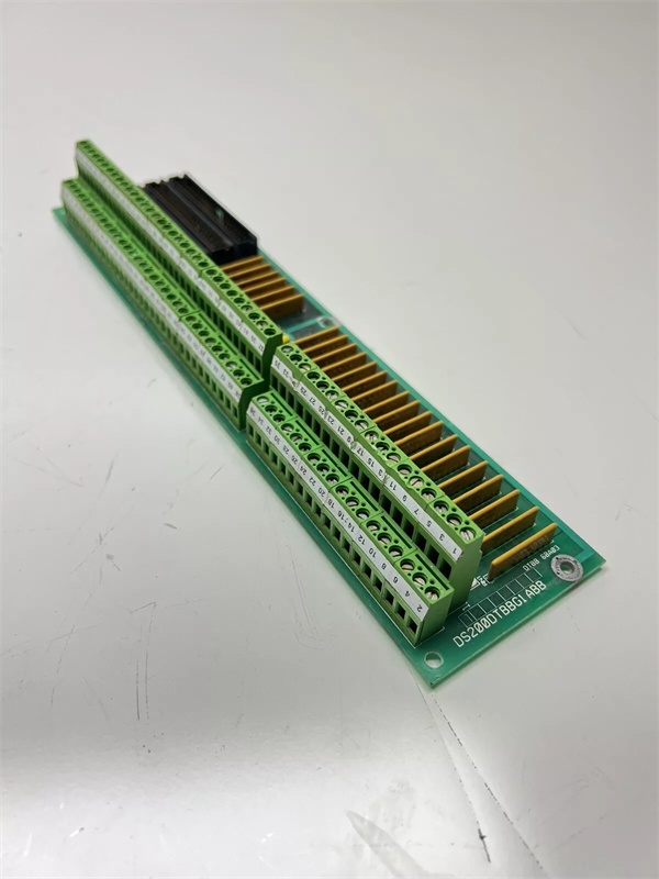
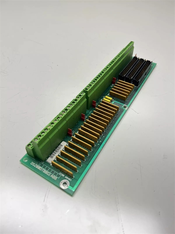
GE DS200DTBBG1ABB
The Real-World Problem It Solves
Mid-voltage drive systems requiring bidirectional power flow need robust power interfaces between control electronics and SCR bridges. The DS200PCCAG1ACB provides the critical gate drive signal isolation and distribution for regenerative applications where power flows in both directions. Its G1 group classification tailors it for 240-630V applications commonly found in turbine excitation and mid-range motor drives.
Where you’ll typically find it:
- Turbine excitation systems in power generation
- Mid-voltage DC motor drives in industrial applications
- Regenerative brake systems in crane and hoist applications
- EX2000 excitation control cabinets
Bottom line: Regenerative power interface for SCR gate control in 240-630V applications.
Hardware Architecture & Under-the-Hood Logic
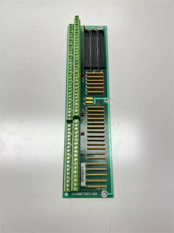
The DS200PCCAG1ACB serves as the interface between the drive control circuitry and the SCR power bridge, transmitting gate drive pulses through pulse transformers for isolation. This Group 1 variant is configured for regenerative operation with both AC and DC snubber networks to protect SCRs from voltage spikes during bidirectional power flow. The board uses line fuses (not leg fuses) for overcurrent protection and supports both separate and common bus transformers. Four configurable jumpers allow site-specific adjustments to capacitor connections and voltage feedback circuitry. The board lacks onboard diagnostic components like LEDs or test points, relying on system-level diagnostics for fault detection.
Signal flow:
- Gate drive control signals received from SDCC drive control board
- Signals routed through pulse transformers for galvanic isolation
- Isolated gate pulses transmitted via 1FPL-6FPL connectors to forward SCR bridge
- Reverse gate pulses transmitted via 1RPL-6RPL connectors for regenerative braking operation
- Power supply communication handled through 5PL connector to DCFB power supply board
- Line fuses provide overcurrent protection on input power lines
- AC and DC snubber networks suppress voltage spikes across SCR devices
- Jumpers JP1 and JP2 configure system voltage and stab terminal connections (P3-P10)
- Jumpers WP3 and WP4 configure snubber capacitor connections relative to voltage feedback channel
- Voltage feedback signals monitored for bridge status and regenerative control
- No onboard LEDs, fuses, or test points—fault detection through system-level monitoring
- Board mounted on board carrier behind drive control board
GE DS200DTBBG1ABB
Field Service Pitfalls: What Rookies Get Wrong
Confusing line fuses with leg fuses causes protection failuresWrong fuse replacement type. I’ve seen technicians replacing blown fuses with leg fuses instead of line fuses, compromising the protection scheme and potentially causing SCR damage.
- Field Rule: G1 boards use line fuses (not leg fuses). G1, G2, G7, and G8 groups have line fuses while G5, G6, G9, and G10 have leg fuses. Verify the exact fuse rating and type for each position. Never substitute leg fuses for line fuses—the protection characteristics differ significantly. Document all fuse ratings during installation. Check line fuses after any overcurrent event.
Misconfiguring WP3/WP4 jumpers causes snubber isolation issuesWrong snubber capacitor connections. I’ve seen technicians setting WP3 and WP4 incorrectly, disconnecting snubber capacitors from the voltage feedback reference point and leaving SCRs vulnerable to voltage spikes.
- Field Rule: WP3 connects P2A to P2B, WP4 connects P1A to P1B. These jumpers determine whether snubber capacitors connect to the same point on the power bridge as the voltage feedback channel. Photograph jumper positions before removal. Never assume default settings match your configuration. Verify snubber connections with the manual based on your group number and system voltage.
Ignoring regenerative polarity causes SCR firing failuresForward/reverse gate pulse reversal. I’ve seen technicians swapping 1FPL and 1RPL connections during installation, causing the drive to fire SCRs in the wrong sequence during regenerative braking.
- Field Rule: Label all gate pulse connectors clearly with their source and destination. 1FPL through 6FPL carry forward gate pulses to the SCR bridge. 1RPL through 6RPL carry reverse gate pulses for regenerative operation. Never rely on connector position alone—verify wiring against the system diagram. Test firing sequence in both directions after installation using a scope.
Assuming G1 compatibility with other groups causes system mismatchWrong group substitution. I’ve seen technicians using a G1 board to replace a G2 or G7 PCCA, resulting in voltage and fuse configuration incompatibilities.
- Field Rule: Match the exact group number when replacing PCCA boards. The G1 designation indicates specific voltage range (240-630V), regenerative operation, line fuse configuration, and snubber types that differ from other groups. Cross-reference the complete part number including the group designation. Never assume group interchangeability even if the connectors look similar.
Forgetting DCFB power supply compatibility causes communication failuresWrong power supply board interface. I’ve seen technicians connecting G1 boards to incompatible power supply boards, causing communication faults through the 5PL connector.
- Field Rule: Verify the system uses a DCFB-compatible power supply board. G1 boards require specific power supply characteristics for proper communication through the 5PL connector. Check the power supply board part number against the system documentation. Never assume all Mark V power supply boards are compatible with all PCCA groups.
Misinterpreting lack of onboard diagnostics as board failureNo LEDs or test points confuse troubleshooting. I’ve seen technicians replacing good boards because they couldn’t diagnose them directly, not realizing PCCA boards rely on system-level diagnostics.
- Field Rule: Use the drive control panel diagnostics to identify PCCA-related faults. The board has no LEDs, test points, or switches for direct troubleshooting. System diagnostics can identify gate pulse issues, SCR firing problems, snubber faults, and communication issues through the 5PL connector. Run full system diagnostics before replacing any PCCA board.
Overlooking snubber capacitor aging causes voltage spike damageDegraded snubber capacitors fail to suppress spikes. I’ve seen technicians replacing PCCA boards without inspecting snubber capacitors, allowing voltage spikes to damage new SCRs.
- Field Rule: Inspect all snubber capacitors for bulging, leakage, or drying during board replacement. Capacitors age faster in high-temperature environments. Test capacitance values if equipment is available. Replace suspect capacitors preventively during board swaps. Never assume capacitors are good just because the old board was working.
Incorrect torque on stab terminals causes voltage feedback errorsLoose P1-P10 stab connections. I’ve seen technicians failing to properly torque the stab terminals, causing intermittent voltage feedback signals and erratic SCR firing.
- Field Rule: Use a torque screwdriver to secure stab terminals to specification. Loose connections cause voltage feedback noise and inaccurate firing timing. Check all P1-P10 terminal connections after installation. Verify torque values match the manual requirements. Never rely on finger-tight connections for power electronics.
Commercial Availability & Pricing Note
Please note: The listed price is for reference only and is not binding. Final pricing and terms are subject to negotiation based on current market conditions and availability.


