
Description
Hard-Numbers: Technical Specifications
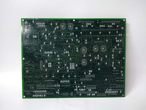
- PCB Dimensions: 3.75 inches square (95.3 mm × 95.3 mm)
- Board Type: Daughterboard mounted to LBC586P/UCIA processor board
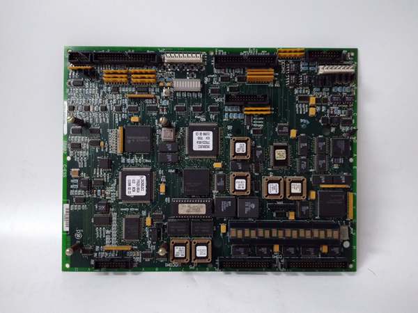
- Connectors: One 40-pin connector, one 64-pin connector
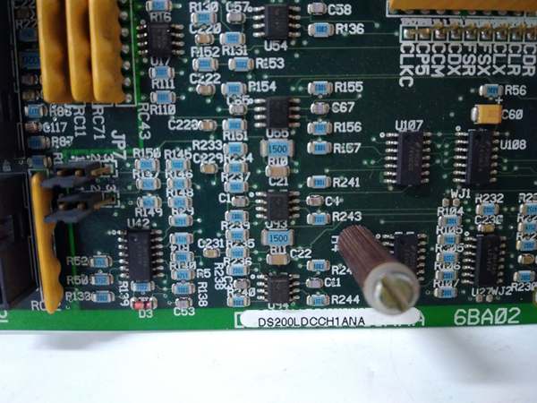
- Configuration Elements: 10 hardware jumpers (JP prefix), 4 DIP switches for ARCNET addressing
- Communication Protocol: ARCNET (2.5 Mbps typical)
- Network Channels: Channel A (Stage Link), Channel B (COREBUS)
- Protection: Conformal coating for moisture/chemical resistance
- Semiconductor Devices: Two RF FET devices for signal amplification
- Power Supply: Powered via host board (LBC586P/UCIA)
- Operating Temperature: 0°C to 60°C (32°F to 140°F)
- Mounting: Four corner holes with insulation for standoff mounting
- Revision: A (first functional revision)
- Manual Reference: GEH-6153 Data Sheet

GE DS200LDCCH1ANA
The Real-World Problem It Solves
Mark V turbine control systems require high-speed, deterministic communication between the central control engine and distributed I/O cores. The DS200PANAH1A provides ARCNET driver functionality, enabling reliable data transmission across COREBUS and Stage Link networks without relying on traditional LAN infrastructure. This board eliminates network complexity by using hardware-based addressing and jumper configuration.
Where you’ll typically find it:
- Mark V gas turbine control cabinets in the <R> core rack
- LBC586P processor board daughterboard mounting location
- EX2000 excitation control systems
- Systems requiring redundant ARCNET communication paths
Bottom line: Hardware-based ARCNET communication bridge for Mark V control systems.
Hardware Architecture & Under-the-Hood Logic
The DS200PANAH1A mounts as a daughterboard to the LBC586P (or UCIA) processor board in the <R> core, acting as the ARCNET network interface controller. It contains RF FET amplifiers for signal conditioning and uses hardware jumpers and DIP switches for configuration—no software setup required. The board manages two independent ARCNET channels: Stage Link (Channel A) for communication with AAHA1 board and COREBUS (Channel B) for AAHA2 board communication. All addressing, interrupt, and I/memory mapping is handled through physical jumper settings that must match the system configuration.
Signal flow:
- Board receives power and data from host LBC586P/UCIA board through P1/P2 bus connectors
- Four DIP switches set ARCNET addresses for Stage Link (first two switches) and COREBUS (last two switches)
- Hardware jumpers configure interrupt, I/O address, and memory address for each ARCNET channel
- Data destined for AAHA1 board processed through APL connector (Channel A – Stage Link)
- Data destined for AAHA2 board processed through BPL connector (Channel B – COREBUS)
- RF FET devices amplify and condition ARCNET signals for transmission
- Incoming ARCNET signals received and conditioned before passing to host processor
- Host processor communicates with PANA through P1/P2 bus connections
- All configuration handled by factory or installer-set hardware jumpers—no software configuration
- Status and diagnostic information accessible through bus interface to processor board
GE DS200LDCCH1ANA
Field Service Pitfalls: What Rookies Get Wrong
Mismatching jumper settings during board replacement causes communication failuresWrong jumper positions on replacement board. I’ve seen technicians installing replacement PANA boards with factory-default jumper settings, causing immediate ARCNET communication failures because the interrupt and memory addresses don’t match the system configuration.
- Field Rule: Photograph the jumper positions on the failed board before removal. Every JP-prefixed jumper must match the original board exactly—these set I/O addresses, interrupts, and memory mapping. Some jumpers are factory-set for test only and cannot be changed. Never assume factory defaults match your system configuration. Document all jumper positions with JP identifiers before starting the swap.
Misconfiguring DIP switch addresses causes network conflictsWrong ARCNET node address settings. I’ve seen technicians setting the four DIP switches incorrectly, resulting in duplicate ARCNET addresses and bringing down the entire communication network.
- Field Rule: Verify DIP switch settings against the system configuration documentation. First two switches set Stage Link (Channel A) address, last two set COREBUS (Channel B) address. Each R core must have unique addresses. Never reuse addresses from adjacent cores. Document the switch positions on the original board before replacement. Test network integrity after installation using ARCNET diagnostic tools.
Improper daughterboard seating causes intermittent bus connectionsBoard not fully seated in connector. I’ve seen technicians rushing installation and leaving the PANA board partially inserted in the LBC586P socket, resulting in intermittent communication faults that are nearly impossible to diagnose.
- Field Rule: Verify the board is fully seated in the daughterboard connector before securing mounting screws. Apply even pressure across the board surface until it bottoms out in the socket. Listen for tactile feedback indicating proper insertion. Inspect connector pins for damage or bending before installation. Never rely on mounting screws alone for electrical contact—the board must seat fully first.
Touching RF FET devices causes ESD damageStatic discharge during handling. I’ve seen technicians handling the PANA board without ESD protection, zapping the RF FET amplifiers and causing permanent signal degradation.
- Field Rule: Always use ESD protection when handling the PANA board. Ground yourself before touching any components. Hold the board by the edges only—never touch the RF FET devices or exposed circuitry. Store boards in anti-static packaging when not installed. Inspect the RF FETs for physical damage before installation. Never handle the board without first discharging static from your body.
Forgetting to verify conformal coating integrity causes corrosionDamaged coating in harsh environments. I’ve seen technicians installing replacement boards without inspecting the conformal coating, resulting in moisture ingress and premature corrosion in high-humidity cabinets.
- Field Rule: Inspect the conformal coating for cracks, chips, or scratches before installation. The coating protects against moisture, dust, and chemical contaminants. If coating is damaged, apply approved conformal coating repair compound or request a replacement board. Document coating condition in maintenance records. Never install boards with compromised coating in harsh environments without repair.
Ignoring corner hole insulation causes ground faultsExposed mounting holes create shorts. I’ve seen technicians installing the board without verifying insulation in the corner mounting holes, resulting in ground faults when metal standoffs contact the board.
- Field Rule: Verify all four corner mounting holes have proper insulation before installation. The holes are factory-insulated for voltage protection. Check for wear or damage to insulation—use insulating washers if needed. Never install the board directly on metal standoffs without insulation. Measure resistance between mounting hole and board ground before installation.
Mixing up APL and BPL connector wiring causes communication cross-talkSwapped ARCNET link connections. I’ve seen technicians connecting APL to the wrong AAHA board and BPL to the wrong core, causing communication cross-talk and system instability.
- Field Rule: APL connects to AAHA1 board (Stage Link – Channel A). BPL connects to AAHA2 board (COREBUS – Channel B). Label cables clearly during removal. Verify cable routing against system documentation. Never swap APL and BPL connections—they are not interchangeable. Test communication on both channels independently after installation.
Over-tightening mounting screws cracks the PCBExcessive torque during installation. I’ve seen technicians over-tightening the daughterboard mounting screws, causing hairline cracks in the PCB and intermittent faults.
- Field Rule: Use minimal torque to secure the mounting screws—just enough to prevent board movement. The daughterboard weight is minimal; excessive force is unnecessary. If screws require excessive torque, check for proper board seating first. Never use power tools on daughterboard mounting screws. Inspect the PCB for stress marks after installation.
Commercial Availability & Pricing Note
Please note: The listed price is for reference only and is not binding. Final pricing and terms are subject to negotiation based on current market conditions and availability.


