
Description
Key Technical Specifications
-
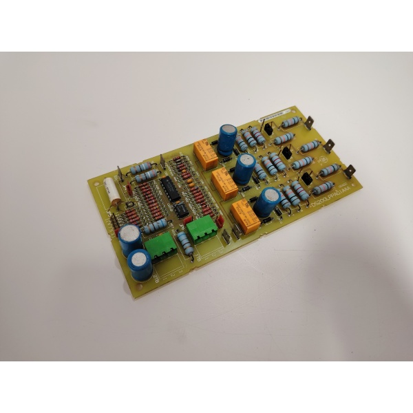
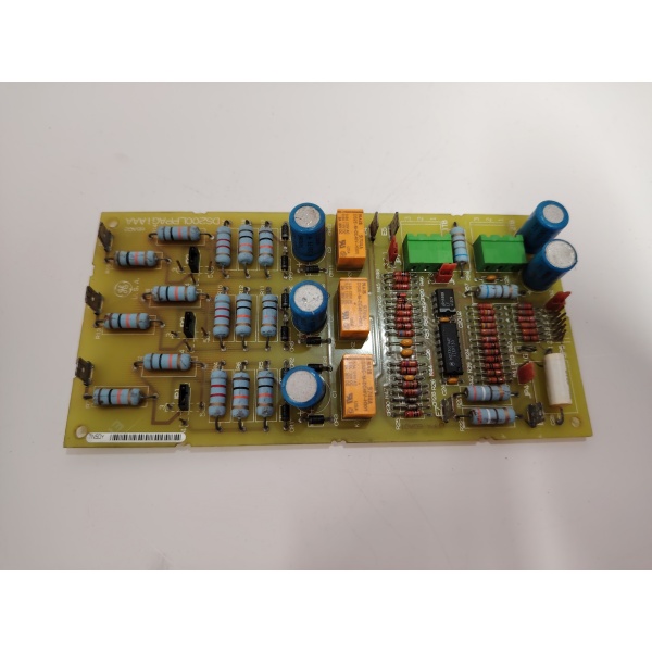
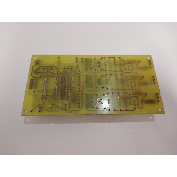
Model Number: DS200LPPAG1AAA
-
Manufacturer: General Electric
-
System Input Range: 200–600 VAC, 3-phase
-
Board Supply: 28 Vdc ±10 %
-
Input Channels: 12 (line-to-line & line-to-neutral via divider network)
-
Output Relay: 125 Vdc, Form-C, 5 A resistive
-
Pick-up Accuracy: ±2 % of set-point
-
Trip Time: ≤10 ms (hardware comparator)
-
Jumpers: JP1–JP7 (voltage range, pickup delay, relay logic)
-
Connectors: Two 3-terminal blocks, chassis-mount stand-offs
-
Isolation: 1500 V input-to-logic
-
Temperature: –40 °C to +85 °C operating
-
Size: 330 × 178 × 25 mm, 0.6 kg

GE DS200LPPAG1AAA
Field Application & Problem Solved
A 7FA compressor package sits on a weak grid; brown-outs sag the 480 V bus just low enough to fold back the DC link but not long enough to trip mains breakers. That’s where this board earns its keep. It watches all three phases through resistor-divider inputs; when any line drops 15 % below nominal for longer than 150 ms (JP3 selects delay) it yanks the coil supply off the main contactor and saves the GTO stack from pulling boost current out of a dying phase. You avoid diode failures that cost a week’s rent on a 1 200 A fuse and a crane call. Same card protects against phase-loss on a 9E during crank — open phase will pull rotor current through two phases only and cook the field; LPPA kills the start before torque builds. Bottom line: cheap board keeps expensive silicon alive.
A 7FA compressor package sits on a weak grid; brown-outs sag the 480 V bus just low enough to fold back the DC link but not long enough to trip mains breakers. That’s where this board earns its keep. It watches all three phases through resistor-divider inputs; when any line drops 15 % below nominal for longer than 150 ms (JP3 selects delay) it yanks the coil supply off the main contactor and saves the GTO stack from pulling boost current out of a dying phase. You avoid diode failures that cost a week’s rent on a 1 200 A fuse and a crane call. Same card protects against phase-loss on a 9E during crank — open phase will pull rotor current through two phases only and cook the field; LPPA kills the start before torque builds. Bottom line: cheap board keeps expensive silicon alive.
Installation & Maintenance Pitfalls (Expert Tips)
Jumpers are NOT optional
JP1-JP7 set voltage window and relay logic. Default is 480 V; if you drop it in a 380 V site without moving JP2 you’ll nuisance-trip every Monday morning when the plant air loads up. Match the jumper table in GEI-100178 before you land wires.
Jumpers are NOT optional
JP1-JP7 set voltage window and relay logic. Default is 480 V; if you drop it in a 380 V site without moving JP2 you’ll nuisance-trip every Monday morning when the plant air loads up. Match the jumper table in GEI-100178 before you land wires.
Tighten stand-off screws first
Chassis mount means the board floats on four 6-32 stand-offs. Snug them 10 in-lb; loose stand-offs crack the PCB when the door slams and you’ll chase intermittent “relay not energized” faults that disappear when you open the cabinet.
Chassis mount means the board floats on four 6-32 stand-offs. Snug them 10 in-lb; loose stand-offs crack the PCB when the door slams and you’ll chase intermittent “relay not energized” faults that disappear when you open the cabinet.
28 Vdc must be clean
Board runs comparators off 28 V. If your DC supply rides a half-wave battery charger you’ll see 5 V ripple, comparators chatter, and the main contactor bucks like a jack-hammer. Meter ripple at <1 % or add a 10 000 µF filter cap across the supply.
Board runs comparators off 28 V. If your DC supply rides a half-wave battery charger you’ll see 5 V ripple, comparators chatter, and the main contactor bucks like a jack-hammer. Meter ripple at <1 % or add a 10 000 µF filter cap across the supply.
Test points lie with blown dividers
GE DS200LPPAG1AAA
The two test points give scaled 4 V for 100 % voltage. If a divider resistor opens (usually R4) you read 0 V, think the line is dead, and start pulling cables. Always meter input across R4-R6 before you trust the test point.
Technical Deep Dive & Overview
DS200LPPAG1AAA is a pure-hardware protection board—no CPU, no firmware. Three-phase voltage feeds precision divider networks that drive LM311 comparators. Reference voltages come from a zener string trimmed by JP4-JP6; when any input drops below reference the comparator fires a one-shot that latches the relay driver transistor. A second comparator checks for over-voltage; both feed the same relay so you get Form-C contacts for under OR over. JP7 selects fail-safe or non-fail-safe logic so you can hold contactor closed on loss of board power if your safety scheme requires it. Because everything is analog, swap time is under a minute: kill 28 V, swap card, restore power—no download, no re-cal.
DS200LPPAG1AAA is a pure-hardware protection board—no CPU, no firmware. Three-phase voltage feeds precision divider networks that drive LM311 comparators. Reference voltages come from a zener string trimmed by JP4-JP6; when any input drops below reference the comparator fires a one-shot that latches the relay driver transistor. A second comparator checks for over-voltage; both feed the same relay so you get Form-C contacts for under OR over. JP7 selects fail-safe or non-fail-safe logic so you can hold contactor closed on loss of board power if your safety scheme requires it. Because everything is analog, swap time is under a minute: kill 28 V, swap card, restore power—no download, no re-cal.


