
Description
Key Technical Specifications
-
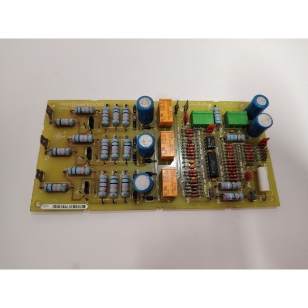
Model Number: DS200LPPAG1A
-
Manufacturer: General Electric (GE)
-
Voltage Rating: 230 VAC max
-
Current Rating: 20 A continuous
-
Jumpers: 7 positions (JP1-JP7) for pickup, time, and function selection
-
Terminal Blocks: 2 × 3-point screw terminals
-
Test Points: Multiple TP for signal injection / verification
-
Isolation: 2 kV basic input-to-logic
-
PCB Coating: Normal thickness, anti-static / moisture barrier
-
Mounting: Stand-offs on Mark V card-file; 178 × 100 mm outline
-
Weight: 0.14 kg
-
Operating Temperature: –40…+70 °C

Field Application & Problem Solved
In a Mark V drive cubicle the biggest headache is losing a phase or pulling high ground-fault current on the 230 V fan / heater bus—one blown fuse and the whole card-file overheats. The DS200LPPAG1A sits across that feed, watches all three legs, and trips the contactor before the fault can cook wiring or downstream transformers. You’ll typically find it bolted to the door sub-panel on 7EA or 9F packages—one board protects the auxiliary supply, reports status over the internal 28 V logic bus, and still meets UL 508 without external CTs. Core value: it collapses a three-phase monitor, over-current relay, and trip relay into one 140-gram card you can swap while the turbine is on turning gear—no re-calibration, no extra hardware.
In a Mark V drive cubicle the biggest headache is losing a phase or pulling high ground-fault current on the 230 V fan / heater bus—one blown fuse and the whole card-file overheats. The DS200LPPAG1A sits across that feed, watches all three legs, and trips the contactor before the fault can cook wiring or downstream transformers. You’ll typically find it bolted to the door sub-panel on 7EA or 9F packages—one board protects the auxiliary supply, reports status over the internal 28 V logic bus, and still meets UL 508 without external CTs. Core value: it collapses a three-phase monitor, over-current relay, and trip relay into one 140-gram card you can swap while the turbine is on turning gear—no re-calibration, no extra hardware.
Installation & Maintenance Pitfalls (Expert Tips)
Jumpers Wrong = No Pick-Up
JP1-JP7 set current level and time curve; flip the card and the silk-screen reads backwards. If you select 10 A on a 20 A heater bus the board never trips and you’ll chase a blown fuse wondering why the protection didn’t open. Match the jumper map in GEI-100178 before you power up.
JP1-JP7 set current level and time curve; flip the card and the silk-screen reads backwards. If you select 10 A on a 20 A heater bus the board never trips and you’ll chase a blown fuse wondering why the protection didn’t open. Match the jumper map in GEI-100178 before you power up.
Terminals Must Be Torqued 0.8 Nm
Under-torque and vibration walks the wire out; over-torque and the 3-point screw block cracks. Use a calibrated driver and stop when the washer flattens—then tug-test every conductor.
Under-torque and vibration walks the wire out; over-torque and the 3-point screw block cracks. Use a calibrated driver and stop when the washer flattens—then tug-test every conductor.
Test Points Live at Line Potential
TP1-TP3 sit behind the front bezel; if you poke them with a scope while the board is powered you’re at 230 VAC. Use a differential probe or de-energize the feed—otherwise the scope ground becomes the fault path.
TP1-TP3 sit behind the front bezel; if you poke them with a scope while the board is powered you’re at 230 VAC. Use a differential probe or de-energize the feed—otherwise the scope ground becomes the fault path.
Forget the Coating Inspection and You’ll Get Tracking
Normal PCB coat is thick but not UV-proof; after five years in a 60 °C cabinet micro-cracks let moisture in and the tracking starts. Visually inspect under UV light at every major—if you see white treeing, replace the card before it fails to ground.
Normal PCB coat is thick but not UV-proof; after five years in a 60 °C cabinet micro-cracks let moisture in and the tracking starts. Visually inspect under UV light at every major—if you see white treeing, replace the card before it fails to ground.
Technical Deep Dive & Overview
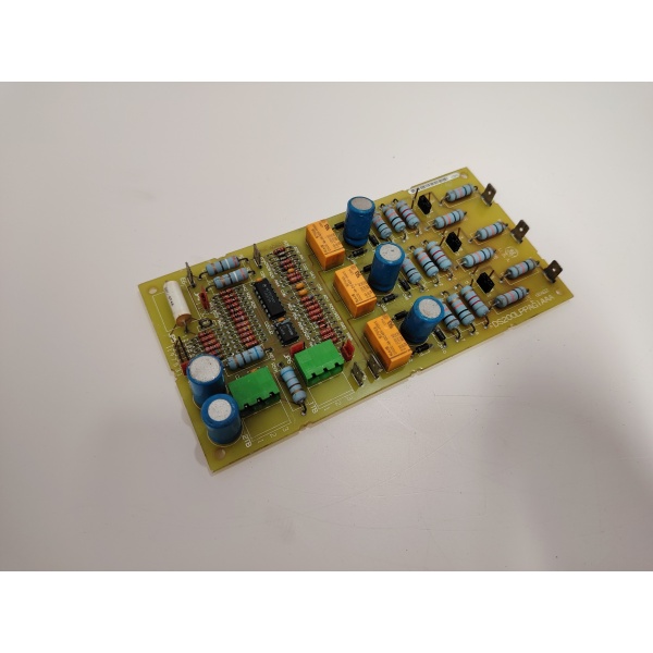
Internally the board is a passive protection array—no CPU, no firmware. Each phase feeds a precision burden resistor, a comparator, and a timer; when current exceeds the jumper-set pickup the comparator pulls in a small relay that drops the 28 VDC contactor coil. An opto-isolator sends the “TRIP” bit to the DSP so the Mark V logs the event. Because it’s hardware you can hot-swap it: pull the old card, land the wires exactly where they came from, snap the plug in, and the protection is live before you close the door
Internally the board is a passive protection array—no CPU, no firmware. Each phase feeds a precision burden resistor, a comparator, and a timer; when current exceeds the jumper-set pickup the comparator pulls in a small relay that drops the 28 VDC contactor coil. An opto-isolator sends the “TRIP” bit to the DSP so the Mark V logs the event. Because it’s hardware you can hot-swap it: pull the old card, land the wires exactly where they came from, snap the plug in, and the protection is live before you close the door
.


