
Description
Hard-Numbers: Technical Specifications
- Bus Architecture: MARK IV/QDII bus architecture
- Processor Type: Dedicated CPU for drive control applications
- Onboard Memory: NVRAM for program storage and configuration retention
- Communication Interfaces: QDII bus for board-to-board communication
- Diagnostics: Front panel indicators for power, status, and fault conditions
- Input Voltage: 24V DC bus power input
- Operating Temperature: 0°C to 50°C (32°F to 122°F)
- Storage Temperature: -40°C to +85°C (-40°F to +185°F)
- Board Dimensions: Standard GE control card form factor
- Update Capability: Firmware updates via QDII bus
- Backup Requirements: Battery-backed memory for parameter retention
- Related Boards: Interfaces with SDCC (Signal Distribution) and FDCA (Data Acquisition) boards
- Parts Manual: GEH-XXXX (consult GE documentation)
- Series Manual: GEH-XXXX Mark IV Maintenance Manual
- Revision Tracking: A suffix indicates revision level compatibility requirements

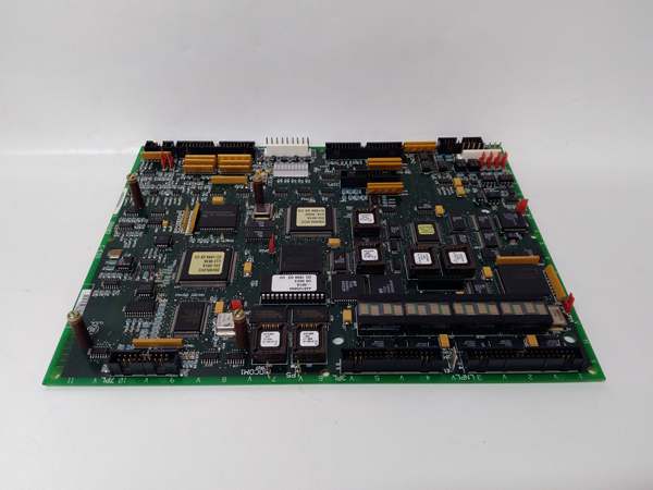
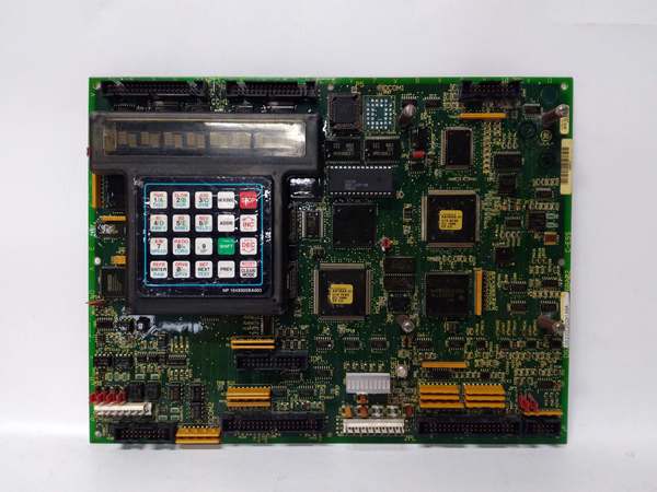
GE DS200LDCCH1A
The Real-World Problem It Solves
LCI systems require precise real-time control coordination for starting large motors and turbine applications. The DS200LDCCH1A serves as the brain of the Mark IV LCI system, executing complex motor control algorithms, managing SCR firing angles, and coordinating with auxiliary boards to ensure reliable static starter operation in industrial environments.
Where you’ll typically find it:
- GE Mark IV LCI static starter control cabinets
- Large motor starting systems (pumps, fans, compressors)
- Turbine starting applications requiring precise torque control
- Industrial drive systems with LCI power converters
Bottom line: Central control processor executing LCI drive algorithms and system coordination logic.
Hardware Architecture & Under-the-Hood Logic
The DS200LDCCH1A is the main CPU board in the GE Mark IV LCI control system hierarchy. It executes the core drive control software, calculating SCR firing angles based on motor speed feedback, current limits, and system setpoints. The board communicates with peripheral boards through the QDII bus architecture, receiving input data from signal distribution boards and sending commands to gate firing boards. The onboard NVRAM stores system parameters and configuration data that must be retained during power cycles. This board is responsible for fault detection, protection logic execution, and system diagnostics, making it the decision-making center of the LCI drive system.
Signal flow:
- Power applied to 24V DC bus input
- CPU initialization sequence loads firmware from NVRAM
- QDII bus communication established with peripheral boards (SDCC, FDCA, etc.)
- Motor feedback signals received through QDII bus interface
- CPU calculates optimal SCR firing angles based on speed/torque requirements
- Firing commands transmitted to gate drive boards via QDII bus
- Status monitoring inputs processed continuously for fault detection
- Protection logic executed if abnormal conditions detected
- Fault logging stored to NVRAM for post-trip analysis
- System status indicators updated on front panel display
- Communication maintained with HMI or external control systems
- Firmware parameters accessible for tuning and configuration adjustments
GE DS200LDCCH1A
Field Service Pitfalls: What Rookies Get Wrong
Pulling the board with system power active causes catastrophic data corruptionLive board removal during operation. I’ve seen technicians removing DS200LDCCH1A without powering down the LCI system, causing NVRAM corruption and requiring complete system reconfiguration.
- Field Rule: Always power down the entire LCI cabinet before removing the CPU board. Verify zero voltage on all bus connections with a multimeter. Wait at least 30 seconds after power-off before disconnecting the board to allow capacitors to discharge. Document the current system configuration before removal. Never hot-swap the CPU board—this is not a hot-pluggable component.
Forgetting to back up NVRAM parameters before replacement causes permanent data lossNo parameter backup before CPU swap. I’ve seen technicians replacing the CPU board without saving critical tuning parameters, resulting in system start-up delays and manual parameter re-entry.
- Field Rule: Always back up all NVRAM parameters using the approved GE utility before removing the CPU board. Document the backup file name and storage location. Verify backup integrity by reading back key parameters. Store backup on external media separate from the cabinet. Never remove the CPU board without creating a verified parameter backup. Have the recovery procedure documented before starting the replacement process.
Improper bus seating causes intermittent communication failuresQDII bus connector not fully engaged. I’ve seen technicians rushing board installation, causing poor contact on the QDII bus connector and resulting in intermittent communication faults.
- Field Rule: Verify the QDII bus connector is fully seated before securing the board. Inspect the connector pins for damage or bending before installation. Apply even pressure when inserting the board—ensure both ends seat simultaneously. Listen for the tactile click indicating proper engagement. Verify communication integrity with system diagnostics after installation. Never assume the board is seated just because mounting screws are tight.
Misinterpreting normal CPU boot-up delays as fault conditionsExtended boot times during power-up. I’ve seen technicians diagnosing faulty boards because the CPU takes longer than expected to initialize, not realizing this is normal during full system boot.
- Field Rule: Understand normal boot-up timing before troubleshooting. The DS200LDCCH1A requires time to initialize all subsystems and establish QDII bus communication. Typical boot-up can take 60-90 seconds depending on system configuration. Monitor front panel LEDs—they indicate specific boot stages. Document normal boot times for each system configuration. Never replace a board based solely on boot duration without checking the LED sequence.
Ignoring battery backup voltage warnings causes NVRAM data lossBackup battery voltage critically low. I’ve seen technicians ignoring low battery warnings, resulting in NVRAM parameter loss during power cycles and extended system downtime.
- Field Rule: Monitor backup battery voltage during routine maintenance. Replace the battery when voltage drops below the specified threshold (typically 2.7V for lithium batteries). Use only approved battery types from GE specifications. Document battery replacement dates and voltage readings. Test NVRAM retention after battery replacement by cycling power. Never allow a low-battery condition to persist beyond one maintenance cycle.
Incorrect firmware version causes system incompatibilityWrong firmware revision installed. I’ve seen technicians upgrading the CPU firmware without verifying compatibility with peripheral boards, causing system-wide communication failures.
- Field Rule: Verify firmware compatibility before any update. Check the firmware version requirements for all boards in the LCI system. Download the correct firmware version from GE’s approved source. Use the recommended firmware update procedure—never force an incompatible version. Document the current and new firmware versions. Test system functionality thoroughly after firmware updates. Never install firmware without first backing up the current version and verifying compatibility.
Improper grounding causes erratic CPU behavior and intermittent faultsPoor board grounding installation. I’ve seen technicians installing the CPU board without ensuring proper ground connections, causing random faults and unpredictable system behavior.
- Field Rule: Verify all ground connections are secure before applying power. Check the grounding strap and backplane connections for corrosion or looseness. Measure ground resistance with a multimeter—should be less than 1 ohm to cabinet ground. Clean ground terminals with contact cleaner if necessary. Document ground resistance readings during installation. Never operate the CPU board without verified proper grounding.
Failing to clear fault latches before restart causes immediate tripOld fault codes still in memory. I’ve seen technicians restarting the system after clearing a fault condition, but the CPU retains the fault latch and immediately trips again.
- Field Rule: Always clear all fault latches in the CPU memory before system restart. Use the approved fault reset procedure—don’t just power cycle. Verify all fault codes are cleared by checking the fault history log. Document all cleared faults for troubleshooting analysis. Never restart the system without confirming all fault latches are reset.
Overlooking watchdog timer issues causes unexplained system resetsCPU watchdog resetting unexpectedly. I’ve seen technicians chasing phantom faults when the CPU watchdog timer is triggering resets due to execution time delays.
- Field Rule: Monitor watchdog timer events in the system diagnostics. Check CPU execution time and interrupt latency if watchdog trips occur frequently. Verify all peripheral boards are responding within expected time windows. Review recent software or parameter changes that may affect CPU loading. Never ignore watchdog events—they indicate real timing or execution problems.
Improper DIP switch settings prevent system bootSwitch configuration incorrect for application. I’ve seen technicians leaving DIP switches at factory default values, causing the CPU to boot into the wrong operational mode.
- Field Rule: Verify DIP switch settings match the system configuration before power-up. Document all switch positions on the replacement board. Compare with the old board’s settings before removal. Use the system configuration documentation as reference. Never power up the CPU board without confirming DIP switch settings.
Commercial Availability & Pricing Note
Please note: The listed price is for reference only and is not binding. Final pricing and terms are subject to negotiation based on current market conditions and availability.


