
Description
Key Technical Specifications
-
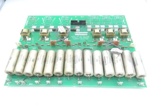
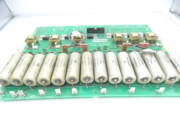
Model Number: DS200IIBDG1ACA
-
Manufacturer: General Electric
-
Control Interface: 15-pin D-sub logic command, 5 V CMOS/TTL
-
Gate Output: ±15 V @ 6 A peak, 6 channels (3 high-side, 3 low-side)
-
Switching Frequency: Factory-limited to 2 kHz in Mark V firmware
-
Desat Threshold: 7 V Vce with 3 µs blanking, latched fault on trip
-
Isolation: 2.5 kV rms, opto-coupled command & status
-
Power Requirement: +5 V logic @ 300 mA, ±15 V isolated gate @ 1.2 A total
-
Operating Temperature: 0 – 70 °C (card edge), derate >55 °C
-
Connectors: J1 logic, J2/J3 gate output, J4 DC link monitor, J5 fiber fault
-
PCB Coating: Standard acrylic, no conformal upgrade
-
Mounting: 6-inch rack slot, captive screws, forced-air cooled rack

GE DS200PCCAG8ACB
Field Application & Problem Solved
In combined-cycle plants the weakest link in the AC2000I exciter/inverter stack is almost never the IGBT brick—it’s the driver. When a gate pulse starts to jitter the brick overheats, the DC link collapses, and the unit trips on “INVERTER FAULT.” The DS200IIBDG1ACA is the board that keeps that from happening. It sits mid-rack, receives 5 V PWM from the <Tool2-TCP>
In combined-cycle plants the weakest link in the AC2000I exciter/inverter stack is almost never the IGBT brick—it’s the driver. When a gate pulse starts to jitter the brick overheats, the DC link collapses, and the unit trips on “INVERTER FAULT.” The DS200IIBDG1ACA is the board that keeps that from happening. It sits mid-rack, receives 5 V PWM from the <Tool2-TCP>
Installation & Maintenance Pitfalls (Expert Tips)
Never Swap Without the Barrier Sheet
The IGBT outline is live at DC link potential. The clear polyester barrier that ships with the new card must be re-installed or the heat sink will arc to the PCB on the first start. I’ve seen the edge of the card blown clean off.
The IGBT outline is live at DC link potential. The clear polyester barrier that ships with the new card must be re-installed or the heat sink will arc to the PCB on the first start. I’ve seen the edge of the card blown clean off.
Tighten the Gate Pins—Then Back Off ¼-Turn
Over-torquing the 4 mm gate/output screws distorts the PCB and cracks internal layers. Snug them, then back off slightly; the spring washer keeps the joint gas-tight without stressing the board.
Over-torquing the 4 mm gate/output screws distorts the PCB and cracks internal layers. Snug them, then back off slightly; the spring washer keeps the joint gas-tight without stressing the board.
Verify Fiber Fault Loop First
The card reports via J5 fiber. If you drop the card in and still get “GATE DRIVE FLT,” swap the fiber Tx/Rx at the <Tool2-TCP>
The card reports via J5 fiber. If you drop the card in and still get “GATE DRIVE FLT,” swap the fiber Tx/Rx at the <Tool2-TCP>
GE DS200PCCAG8ACB
Check Desat Blanking Cap
C17 (100 pF) sets the 3 µs blanking. After 40 k hours the dielectric drifts; the desat trips early and gives you nuisance faults. If the scope shows <2 µs blanking, replace C17 before you condemn a perfectly good gate driver.
C17 (100 pF) sets the 3 µs blanking. After 40 k hours the dielectric drifts; the desat trips early and gives you nuisance faults. If the scope shows <2 µs blanking, replace C17 before you condemn a perfectly good gate driver.
Technical Deep Dive & Overview
The DS200IIBDG1ACA is a six-channel, half-bridge gate driver built on a four-layer FR-4 card. Command pulses enter on J1, pass through HCPL-2630 opto-couplers for isolation, then feed IR2110-style high/low-side drivers. Each channel has its own isolated ±15 V DC-DC converter (Push-pull, 50 kHz) so the upper IGBT emitter can swing from –5 V to +1200 V without disturbing the logic side. Local desat detection compares collector voltage to an internal 7 V reference; when Vce climbs above that during on-time the HCPL-2531 latches a fault that shuts off all six channels and yanks the hard-wired emergency stop line low. Status is echoed back over the same fiber that carries turbine speed data, so the <Tool2-TCP>
The DS200IIBDG1ACA is a six-channel, half-bridge gate driver built on a four-layer FR-4 card. Command pulses enter on J1, pass through HCPL-2630 opto-couplers for isolation, then feed IR2110-style high/low-side drivers. Each channel has its own isolated ±15 V DC-DC converter (Push-pull, 50 kHz) so the upper IGBT emitter can swing from –5 V to +1200 V without disturbing the logic side. Local desat detection compares collector voltage to an internal 7 V reference; when Vce climbs above that during on-time the HCPL-2531 latches a fault that shuts off all six channels and yanks the hard-wired emergency stop line low. Status is echoed back over the same fiber that carries turbine speed data, so the <Tool2-TCP>


