
Description
Key Technical Specifications
-
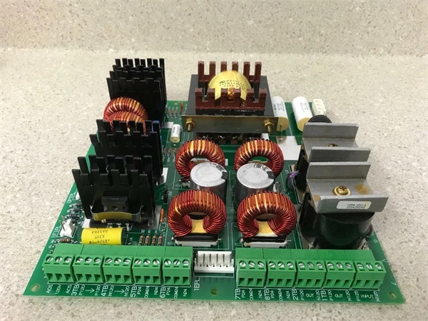
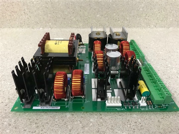
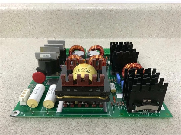
Model Number: DS200IIBDG1A
-
Manufacturer: General Electric (GE)
-
Channels: 6 gate drives (3 phases × high-side + low-side)
-
Gate Output: ±15 V pulse, 6 A peak, 50 kHz max carrier
-
Isolation: 2 kV basic gate-to-logic; optical couplers per channel
-
Feedback: On-board VCO converts ±500 mV shunt to 0-500 kHz diff signal for current loop
-
Voltage Feedback: Isolated motor-terminal voltage divider (0-10 V to DSP)
-
Status LEDs: 9 red LEDs (gate OK, fault, power per phase) visible through card-slot opening
-
Connectors: 96-pin DIN 41612 to VME back-plane; screw terminals for gate & shunt inputs
-
Operating Temperature: –40 °C…+70 °C
-
Dimensions / Weight: 159 × 178 mm, 2 lb (0.9 kg)
- Protection: Desat detection, gate-under-voltage lockout, short-circuit soft-shutdown

Field Application & Problem Solved
In the field the biggest headache is turning on six 400 A IGBTs in the same bridge without blowing devices out of the heat-sink. The board solves that by giving each IGBT its own opto-isolated gate drive plus trim-able dead-time. You’ll typically find one card per six-pulse bridge on 7EA peakers—one board replaces six individual gate amplifiers, a high-voltage isolator, and a current-feedback VCO. Core value: it collapses gate drive, current isolation, and fault feedback into one plug-in card you can swap in five minutes while the unit is on turning gear
In the field the biggest headache is turning on six 400 A IGBTs in the same bridge without blowing devices out of the heat-sink. The board solves that by giving each IGBT its own opto-isolated gate drive plus trim-able dead-time. You’ll typically find one card per six-pulse bridge on 7EA peakers—one board replaces six individual gate amplifiers, a high-voltage isolator, and a current-feedback VCO. Core value: it collapses gate drive, current isolation, and fault feedback into one plug-in card you can swap in five minutes while the unit is on turning gear
.
Installation & Maintenance Pitfalls (Expert Tips)
Gate Leads Must Be Twisted Pair – No Exceptions
The output is a 15 V, 6 A pulse. Run the leads untwisted and the dv/dt couples into the 5 V logic, giving you random “gate fault” trips every time the bridge fires. Use 18 AWG shielded twisted pair, ground the shield at the card end only, and keep the run under 1 m
The output is a 15 V, 6 A pulse. Run the leads untwisted and the dv/dt couples into the 5 V logic, giving you random “gate fault” trips every time the bridge fires. Use 18 AWG shielded twisted pair, ground the shield at the card end only, and keep the run under 1 m
.
Trim Pots Snap at 0.4 Nm
The six surface-mount pots are brass—crank them with a big screwdriver and the slot strips. Use a jeweler’s screwdriver, watch the gate waveform on a differential probe, and stop when the rise-times match within 200 ns. Lock-tite the threads so vibration can’t walk the setting
The six surface-mount pots are brass—crank them with a big screwdriver and the slot strips. Use a jeweler’s screwdriver, watch the gate waveform on a differential probe, and stop when the rise-times match within 200 ns. Lock-tite the threads so vibration can’t walk the setting
.
Desat Fault Latches – Reset Before You Re-Fire
If the IGBT sees collector-emitter saturation the card shuts down and latches. You must cycle 28 VDC on the reset line or the Mark V will keep throwing “Gate FLT” even after you swap the device. Reset it once, then re-enable the bridge.
If the IGBT sees collector-emitter saturation the card shuts down and latches. You must cycle 28 VDC on the reset line or the Mark V will keep throwing “Gate FLT” even after you swap the device. Reset it once, then re-enable the bridge.
LED “Gate OK” Lies If the Opto Is Dead
Green LED only means the opto LED is lit; if the opto transistor fails the DSP still sees “healthy” while the gate never turns on. Meter the D-Sub pins during a brake test—if you don’t see the transistor pull low, replace the card before you blow the IGBT on start-up
Green LED only means the opto LED is lit; if the opto transistor fails the DSP still sees “healthy” while the gate never turns on. Meter the D-Sub pins during a brake test—if you don’t see the transistor pull low, replace the card before you blow the IGBT on start-up
.
Technical Deep Dive & Overview
Internally the card is six high-side/low-side gate drivers bolted to a 2 kV isolation barrier. Each channel uses a forward converter to generate +15 V and –5 V from the 24 V back-plane; the on-board VCO converts shunt voltage to frequency so the DSP can close the current loop. An opto-coupler sends “gate OK” and desat status back to the DSP; lose the opto and the Mark V throws “Gate FLT” even if the device is fine. No firmware—pure hardware—so you can swap it without reloading parameters; just remember to re-trim every gate or the bridge will eat itself on the first pulse
Internally the card is six high-side/low-side gate drivers bolted to a 2 kV isolation barrier. Each channel uses a forward converter to generate +15 V and –5 V from the 24 V back-plane; the on-board VCO converts shunt voltage to frequency so the DSP can close the current loop. An opto-coupler sends “gate OK” and desat status back to the DSP; lose the opto and the Mark V throws “Gate FLT” even if the device is fine. No firmware—pure hardware—so you can swap it without reloading parameters; just remember to re-trim every gate or the bridge will eat itself on the first pulse
.


