
Description
Key Technical Specifications
-
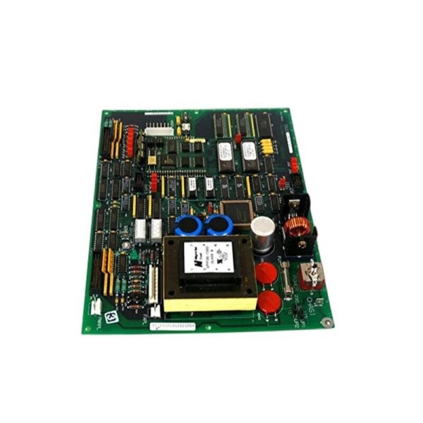
Model Number: DS200GSIAG1A
-
Manufacturer: General Electric (GE)
-
DC Bus Voltage: 400-690 VDC continuous, 1000 VDC 1 min
-
Peak Current: 2 kA for 10 ms (brake-chopper pulse)
-
Isolation: 2 kV basic bus-to-logic; opto-coupled status
-
Brake-Chopper: On-board IGBT, 40 kHz, duty 0-95 %, external brake-resistor connection
-
Connectors: 2 × bus-bar lugs (DC+ / DC–), 1 × 34-pin control header, 2 × 9-pin status D-Subs
-
Protection: Desat, bus-OV, over-temp, short-circuit; auto-shutdown with fault LED
-
Operating Temperature: –40 °C…+70 °C
-
Dimensions / Weight: 159 × 178 mm, 0.7 kg (0.32 kg core board)
-
Mounting: Mark V card-file; stand-offs at corners
-
Certifications: CE, UL508, IEC 61010-1

GE DS200UPLAG1B
Field Application & Problem Solved
In medium-voltage EX2000 / AC2000 drives the biggest headache is managing the common DC bus—absorbing regen energy from the motor and keeping bus voltage below 800 V when the load decelerates. The DS200GSIAG1A sits across the DC link: when the bus climbs above the set-point the on-board brake-chopper dumps energy into an external resistor bank, while the opto-isolators keep the 690 V bus away from the 5 V logic. You’ll typically find one card per common-bus section on Frame-7/9 peakers—swap it while the unit is on turning gear and you still meet UL isolation without external hardware. Core value: it collapses a brake-chopper, bus-bar isolator, and fault annunciator into one 0.7 kg card you can swap in five minutes.
In medium-voltage EX2000 / AC2000 drives the biggest headache is managing the common DC bus—absorbing regen energy from the motor and keeping bus voltage below 800 V when the load decelerates. The DS200GSIAG1A sits across the DC link: when the bus climbs above the set-point the on-board brake-chopper dumps energy into an external resistor bank, while the opto-isolators keep the 690 V bus away from the 5 V logic. You’ll typically find one card per common-bus section on Frame-7/9 peakers—swap it while the unit is on turning gear and you still meet UL isolation without external hardware. Core value: it collapses a brake-chopper, bus-bar isolator, and fault annunciator into one 0.7 kg card you can swap in five minutes.
Installation & Maintenance Pitfalls (Expert Tips)
Bus Bars Float at 690 V – Short Them Last
The DC+ and DC– lugs sit at bridge potential; if you land the cables while the bus is hot you’ll arc-weld the 2 kV isolator. De-energize, wait for bus < 50 V, then torque lugs to 0.8 Nm or vibration will walk them out
The DC+ and DC– lugs sit at bridge potential; if you land the cables while the bus is hot you’ll arc-weld the 2 kV isolator. De-energize, wait for bus < 50 V, then torque lugs to 0.8 Nm or vibration will walk them out
.
Brake Resistor Must Be Sized Correctly
The chopper is rated 2 kA peak for 10 ms. If you connect a 10 Ω resistor on a 690 V bus the pulse is 69 A—well within limit—but if you forget the resistor the IGBT avalanches and the card is scrap. Ohm it out before first fire-up.
The chopper is rated 2 kA peak for 10 ms. If you connect a 10 Ω resistor on a 690 V bus the pulse is 69 A—well within limit—but if you forget the resistor the IGBT avalanches and the card is scrap. Ohm it out before first fire-up.
Status LED Lies If the Opto Is Dead
Green “OK” only means the opto LED is lit; if the opto transistor fails the DSP still sees “healthy” while the chopper never fires. Meter the D-Sub pins during a brake test—if you don’t see the transistor pull low, replace the card.
Green “OK” only means the opto LED is lit; if the opto transistor fails the DSP still sees “healthy” while the chopper never fires. Meter the D-Sub pins during a brake test—if you don’t see the transistor pull low, replace the card.
Convection Only – Don’t Block the Slots
The card relies on rack airflow; if you leave a blank filler plate above or below the heat-sink hits 85 °C and the OTP trips. Keep one empty slot on each side or add a 24 VDC muffin fan if the cabinet runs hot.
The card relies on rack airflow; if you leave a blank filler plate above or below the heat-sink hits 85 °C and the OTP trips. Keep one empty slot on each side or add a 24 VDC muffin fan if the cabinet runs hot.
Technical Deep Dive & Overview
Internally the board is a high-voltage IGBT chopper bolted to a 2 kV isolation barrier. When bus voltage exceeds the jumper-set threshold the DSP fires the IGBT, dumping energy into the external resistor; the duty cycle is limited to 95 % to prevent continuous conduction. An opto-coupler sends “chopper OK” back to the DSP; lose the opto and the Mark V throws “GSI FLT” even if the chopper is fine. No firmware—pure hardware—so you can swap it without reloading parameters; just remember to torque the bus bars or the DC link will arc on the first pulse.
Internally the board is a high-voltage IGBT chopper bolted to a 2 kV isolation barrier. When bus voltage exceeds the jumper-set threshold the DSP fires the IGBT, dumping energy into the external resistor; the duty cycle is limited to 95 % to prevent continuous conduction. An opto-coupler sends “chopper OK” back to the DSP; lose the opto and the Mark V throws “GSI FLT” even if the chopper is fine. No firmware—pure hardware—so you can swap it without reloading parameters; just remember to torque the bus bars or the DC link will arc on the first pulse.


