
Description
Key Technical Specifications
-
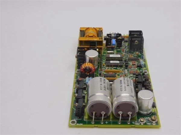
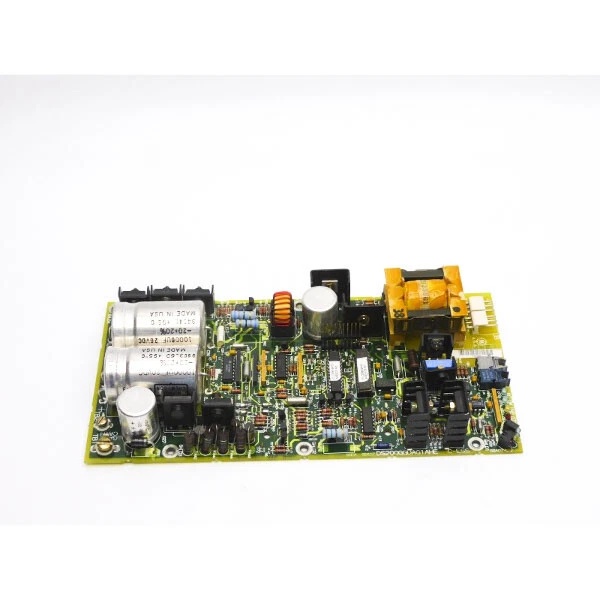
Model Number: DS200GGDAG1AHE
-
Manufacturer: General Electric
-
Logic Supply: 24 Vdc ±20 %
-
Gate Supply: ±15 Vdc (on-board DC-DC)
-
Peak Output Current: ±15 A per channel
-
Switching Frequency: 20 kHz max
-
Power Devices Driven: 4500 V GTO thyristors
-
Isolation: 1500 Vdc gate-to-logic
-
Status Indicators: 2 groups of 4 LEDs (1 red, 1 amber, 2 green each)
-
Connectors: 2×3-pin gate leads, 2×bayonet coax for current feedback
-
Operating Temperature: 0 – 60 °C
-
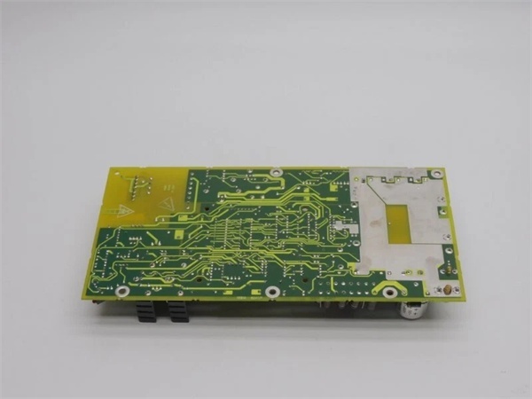
Board Size: 245 × 185 × 25 mm, 1.47 kg
-
Mounting: Plug-in on 2PL back-plane, captive screws

GE DS200GGDAG1AHE
Field Application & Problem Solved
In a 7EA peaker the DC link is held up by a six-pulse GTO bridge. When the Mark V wants to ram 2 500 A into the field, it doesn’t send volts—it sends a 12 µs gate pulse. This board turns that 5 V logic edge into a 15 A punch that punches through the GTO’s 3 V gate junction. Lose the gate driver and the bridge freewheels; you get a DC link under-voltage trip and the unit drops offline. Swap the card, hit reset, and the turbine is back to base load in five minutes. That’s why every peaker crate keeps a spare GGDAG taped inside the door.
In a 7EA peaker the DC link is held up by a six-pulse GTO bridge. When the Mark V wants to ram 2 500 A into the field, it doesn’t send volts—it sends a 12 µs gate pulse. This board turns that 5 V logic edge into a 15 A punch that punches through the GTO’s 3 V gate junction. Lose the gate driver and the bridge freewheels; you get a DC link under-voltage trip and the unit drops offline. Swap the card, hit reset, and the turbine is back to base load in five minutes. That’s why every peaker crate keeps a spare GGDAG taped inside the door.
Installation & Maintenance Pitfalls (Expert Tips)
Gate leads are twisted-pair—don’t extend them
The 3-pin leads are factory-cut to 18″. Lengthen them and the added inductance rings the gate at 40 V; you’ll split the GTO’s emitter bond wires. Route the original harness exactly as shipped.
Gate leads are twisted-pair—don’t extend them
The 3-pin leads are factory-cut to 18″. Lengthen them and the added inductance rings the gate at 40 V; you’ll split the GTO’s emitter bond wires. Route the original harness exactly as shipped.
Bayonet coax must click twice
Current feedback rides those bayonets. A half-turn gives you 30 % ripple on the waveform; the Mark V thinks the bridge is faulted and trips on “OVER-I”. Twist until you feel the second detent.
Current feedback rides those bayonets. A half-turn gives you 30 % ripple on the waveform; the Mark V thinks the bridge is faulted and trips on “OVER-I”. Twist until you feel the second detent.
LEDs only tell half the story
Green LEDs mean the board has ±15 V; they do NOT prove gate current. If you still get “GTO FAIL,” meter the gate lead with a Pearson probe—expect 8–12 A peak during turn-on. No current = open lead or dried-out DC-DC cap.
Green LEDs mean the board has ±15 V; they do NOT prove gate current. If you still get “GTO FAIL,” meter the gate lead with a Pearson probe—expect 8–12 A peak during turn-on. No current = open lead or dried-out DC-DC cap.
DC-DC caps age at 55 °C
The on-board 47 µF, 35 V tantalums hit 50 °C inside an IP-54 cabinet. ESR doubles every 10 °C. After 40 k hours the gate current sags and you’ll fire only four of six devices. Replace all four during major—five minutes of SMD beats a forced outage.
The on-board 47 µF, 35 V tantalums hit 50 °C inside an IP-54 cabinet. ESR doubles every 10 °C. After 40 k hours the gate current sags and you’ll fire only four of six devices. Replace all four during major—five minutes of SMD beats a forced outage.
GE DS200GGDAG1AHE
Technical Deep Dive & Overview
The board is a two-channel gate amplifier with isolated DC-DC converters. A 250 kHz forward converter generates ±15 V from the 24 V logic rail; gate pulses are capacitively coupled through pulse transformers to keep 1500 V isolation. Two high-speed MOSFET stages dump 15 A into the GTO gate in < 1 µs, then pull –15 A for turn-off to guarantee storage-time reduction. Current feedback is returned via coax to the SDCC card so the DSP can verify conduction; if the Pearson coil sees < 6 A the Mark V flags “GTO NOT FIRE” and blocks the next firing pulse. No micro on-board—just comparators and drivers—so it hot-swaps without a download.
The board is a two-channel gate amplifier with isolated DC-DC converters. A 250 kHz forward converter generates ±15 V from the 24 V logic rail; gate pulses are capacitively coupled through pulse transformers to keep 1500 V isolation. Two high-speed MOSFET stages dump 15 A into the GTO gate in < 1 µs, then pull –15 A for turn-off to guarantee storage-time reduction. Current feedback is returned via coax to the SDCC card so the DSP can verify conduction; if the Pearson coil sees < 6 A the Mark V flags “GTO NOT FIRE” and blocks the next firing pulse. No micro on-board—just comparators and drivers—so it hot-swaps without a download.


