
Description
Key Technical Specifications
-
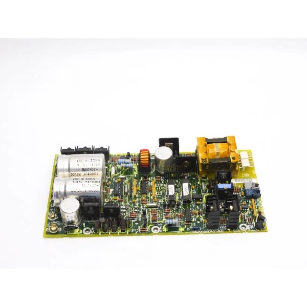
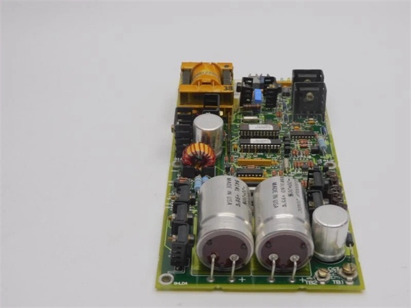
Model Number: DS200GGDAG1A
-
Manufacturer: General Electric (GE)
-
Output Voltage / Current: 240 VDC, 6 A peak per channel
-
Isolation: 2 kV basic gate-to-logic
-
Connectors: 2 × 3-pin screw terminals, 2 × bayonet (gate out), 1 × 34-pin control header
-
Gate Trim: 6 surface-mount pots for turn-on / turn-off timing balance
-
Status LEDs: 2 groups (red, amber, 2 green) per channel for gate OK / fault
-
Switching Frequency: Up to 500 Hz (GTO limited)
-
Operating Temperature: –40 °C…+70 °C
-
Dimensions / Weight: 159 × 178 mm, 1 lb (0.45 kg)
-
Mounting: Mark V card-file; stand-offs at corners
- PCB Coating: Normal thickness, anti-static / moisture barrier

Field Application & Problem Solved
Medium-voltage EX2000 / EX2100 drives use giant GTO thyristors that need a 6 A, 240 V pulse to turn on and a reverse gate spike to turn off. The biggest headache is getting that pulse to the device without ringing or unequal timing—one device that turns on 2 µs late takes the whole bridge current and explodes. Drop the DS200GGDAG1A into the rack: the on-board pots let you trim each gate so all six devices switch within 500 ns, the 2 kV isolator keeps the 690 V bridge away from the 24 V logic, and the LEDs tell you at a glance which gate is weak. You’ll typically find one card per six-pulse bridge on 7FA peakers—swap time is five minutes with the unit on turning gear. Core value: it collapses six individual gate amplifiers, a high-voltage isolator, and a timing network into one plug-in card you can carry in your shirt pocket.
Medium-voltage EX2000 / EX2100 drives use giant GTO thyristors that need a 6 A, 240 V pulse to turn on and a reverse gate spike to turn off. The biggest headache is getting that pulse to the device without ringing or unequal timing—one device that turns on 2 µs late takes the whole bridge current and explodes. Drop the DS200GGDAG1A into the rack: the on-board pots let you trim each gate so all six devices switch within 500 ns, the 2 kV isolator keeps the 690 V bridge away from the 24 V logic, and the LEDs tell you at a glance which gate is weak. You’ll typically find one card per six-pulse bridge on 7FA peakers—swap time is five minutes with the unit on turning gear. Core value: it collapses six individual gate amplifiers, a high-voltage isolator, and a timing network into one plug-in card you can carry in your shirt pocket.
Installation & Maintenance Pitfalls (Expert Tips)
Gate Leads Must Be Twisted Pair – No Exceptions
The output is a 240 V, 6 A spike. Run the leads untwisted and the dv/dt couples into the 24 V logic, giving you random “gate fault” trips every time the bridge fires. Use 18 AWG shielded twisted pair, ground the shield at the card end only, and keep the run under 1 m.
The output is a 240 V, 6 A spike. Run the leads untwisted and the dv/dt couples into the 24 V logic, giving you random “gate fault” trips every time the bridge fires. Use 18 AWG shielded twisted pair, ground the shield at the card end only, and keep the run under 1 m.
Trim Pots Snap at 0.4 Nm
The six surface-mount pots are brass—crank them with a big screwdriver and the slot strips. Use a jeweler’s screwdriver, watch the gate waveform on a differential probe, and stop when the rise-times match within 200 ns. Lock-tite the threads so vibration can’t walk the setting.
The six surface-mount pots are brass—crank them with a big screwdriver and the slot strips. Use a jeweler’s screwdriver, watch the gate waveform on a differential probe, and stop when the rise-times match within 200 ns. Lock-tite the threads so vibration can’t walk the setting.
Bayonet Connectors Back Out with Vibration
The two bayonet outputs look locked until you see 2 mm of silver—enough to arc and weld the pin. Push until you hear the click, then give the collar a quarter-turn tug test. If it moves, replace the connector; a loose gate will blow the GTO at the next load rejection.
The two bayonet outputs look locked until you see 2 mm of silver—enough to arc and weld the pin. Push until you hear the click, then give the collar a quarter-turn tug test. If it moves, replace the connector; a loose gate will blow the GTO at the next load rejection.
LED “Gate OK” Lies If the Pot Is Drifted
After 5 years at 60 °C the carbon film drifts high; the LED still glows green but the gate current is 4 A instead of 6 A. During every major outage scope the gate resistor voltage and re-trim if the current is off by more than 5 %. Otherwise you’ll discover the weakness when the device fails short on start-up.
After 5 years at 60 °C the carbon film drifts high; the LED still glows green but the gate current is 4 A instead of 6 A. During every major outage scope the gate resistor voltage and re-trim if the current is off by more than 5 %. Otherwise you’ll discover the weakness when the device fails short on start-up.
Technical Deep Dive & Overview
Internally the card is a set of six high-side gate drivers bolted to a 2 kV isolation barrier. Each channel uses a small forward converter to generate +240 V and –40 V from the 24 V back-plane; the trim pot sets the gate resistor value so the RC time constant matches the device’s turn-on / turn-off characteristic. An opto-coupler sends the “gate OK” status back to the DSP; lose the opto and the Mark V throws “Gate Fault” even if the device is fine. No firmware—pure hardware—so you can swap the card without reloading parameters; just remember to re-trim every gate or the bridge will eat itself on the first pulse.
Internally the card is a set of six high-side gate drivers bolted to a 2 kV isolation barrier. Each channel uses a small forward converter to generate +240 V and –40 V from the 24 V back-plane; the trim pot sets the gate resistor value so the RC time constant matches the device’s turn-on / turn-off characteristic. An opto-coupler sends the “gate OK” status back to the DSP; lose the opto and the Mark V throws “Gate Fault” even if the device is fine. No firmware—pure hardware—so you can swap the card without reloading parameters; just remember to re-trim every gate or the bridge will eat itself on the first pulse.


