
Description
Key Technical Specifications
-
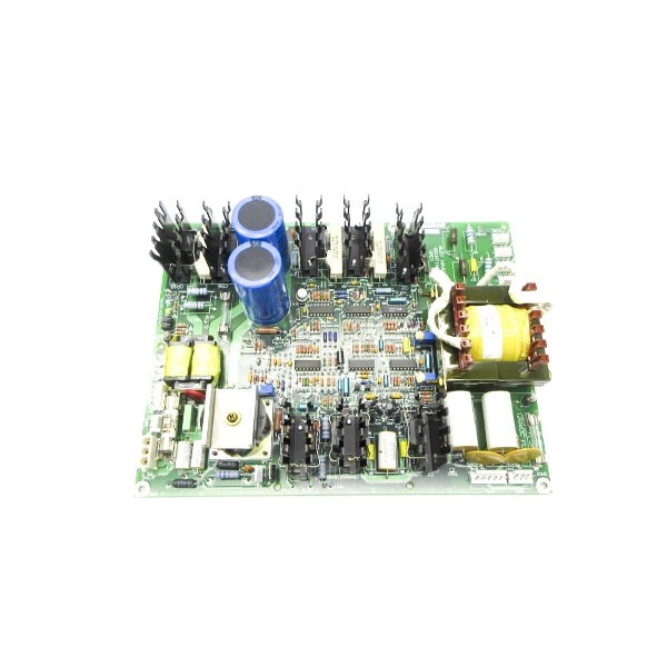
Model Number: DS200GDPAG1ALF
-
Manufacturer: General Electric (GE)
-
Input Voltage: 80-132 VAC (50/60 Hz) or 105-140 VDC
-
Output Rails:
-
120 VDC @ 5 A (gate / contactor bus)
-
50 VAC @ 3 A (auxiliary transformer secondaries)
-
+5 V @ 10 A (logic) derived on daughter PCB
-
-
Power Rating: 600-700 W continuous
-
Switching Frequency: 27 kHz forward converter with buck driver
-
Efficiency: ≈ 92 % @ 50 % load; active PFC on AC input
-
Isolation: Basic insulation 2 kV input-to-output; transformer-coupled secondaries
-
Protection Circuits: Inverter over-current, regulator over-current, P80 over-voltage, control-voltage UV, CVOK running signal
-
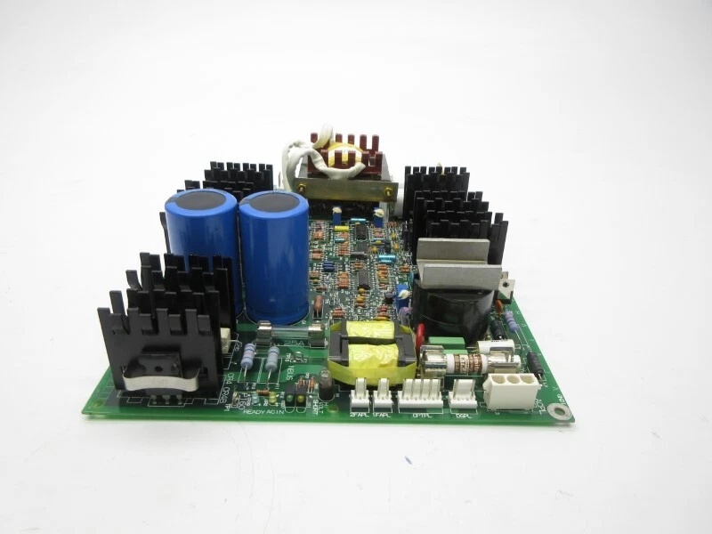
Connectors: 4 × GXPL screw terminals, 2 × stab-on AC inputs, 1 × 12-pin control header, multiple TP test points
-
Operating Temperature: –40 °C…+70 °C (derate > 60 °C)
-
Dimensions / Weight: 16 × 16 × 12 cm, 0.8 kg
-
Mounting: Mark V card-file; four corner screws or stand-offs in drive cabinet
-
Status: Factory discontinued – new & tested spares available

GE DS200GDPAG1ALF
Field Application & Problem Solved
In the field the biggest headache is keeping the 120 VDC contactor bus alive when the station battery sags or the AC feeder browns out. The DS200GDPAG1ALF solves that by living inside the same rack as the Mark V CPU—it will run on either the 125 VDC battery or the 110 VAC station service, so you never lose gate drive during a transfer. You’ll typically find one bolted behind the left-hand door on Frame-7/9 peakers: one board feeds the IGBT gate drivers, the 50 VAC auxiliary transformer, and the +5 V logic daughter card. Core value: it collapses a battery charger, a 50 Hz step-down, and a 27 kHz switcher into one 0.8 kg card you can swap while the turbine is on turning gear
In the field the biggest headache is keeping the 120 VDC contactor bus alive when the station battery sags or the AC feeder browns out. The DS200GDPAG1ALF solves that by living inside the same rack as the Mark V CPU—it will run on either the 125 VDC battery or the 110 VAC station service, so you never lose gate drive during a transfer. You’ll typically find one bolted behind the left-hand door on Frame-7/9 peakers: one board feeds the IGBT gate drivers, the 50 VAC auxiliary transformer, and the +5 V logic daughter card. Core value: it collapses a battery charger, a 50 Hz step-down, and a 27 kHz switcher into one 0.8 kg card you can swap while the turbine is on turning gear
.
Installation & Maintenance Pitfalls (Expert Tips)
Input Fuse Is Potted – Don’t Blow It
The mains fuse is under conformal coat; short the output and the board is scrap. Always megger the load cables before first power-up; a grounded 120 VDC fan lead will blow the fuse and you’ll chase a “supply fail” that can’t be field-repaired
The mains fuse is under conformal coat; short the output and the board is scrap. Always megger the load cables before first power-up; a grounded 120 VDC fan lead will blow the fuse and you’ll chase a “supply fail” that can’t be field-repaired
.
AC Below 102 VAC = Thermal Runaway
The board will start at 80 VAC but full-load below 102 VAC causes the heat-sink to climb above 85 °C and the OTP trips. If your station service dips, either shed load or add a buck transformer or you’ll discover the weakness during a brown-out
The board will start at 80 VAC but full-load below 102 VAC causes the heat-sink to climb above 85 °C and the OTP trips. If your station service dips, either shed load or add a buck transformer or you’ll discover the weakness during a brown-out
.
GE DS200GDPAG1ALF
GXPL Terminals Walk Out with Vibration
The four screw terminals are 6 mm² GXPL; torque to 0.8 Nm and tug-test every wire. Under-torque and the 120 VDC lead arcs to the cabinet wall—ground fault that trips the whole Mark V.
The four screw terminals are 6 mm² GXPL; torque to 0.8 Nm and tug-test every wire. Under-torque and the 120 VDC lead arcs to the cabinet wall—ground fault that trips the whole Mark V.
Test Points Are Live at 170 VDC
TP1-TP6 sit behind the front bezel; if you poke them with a scope while the board is powered you’re at rectified DC potential. Use a differential probe or pull the card first—otherwise the scope ground becomes the fault path.
TP1-TP6 sit behind the front bezel; if you poke them with a scope while the board is powered you’re at rectified DC potential. Use a differential probe or pull the card first—otherwise the scope ground becomes the fault path.
Technical Deep Dive & Overview
Internally the card is a 27 kHz forward-converter SMPS. The primary side rectifies 80-132 VAC (or 105-140 VDC), feeds a MOSFET switch, and delivers 120 VDC and 50 VAC through separate secondary windings. Opto-couplers report “CVOK” and fuse status to the DSP; lose any rail and the Mark V throws “GDP FAIL” within 50 ms. No fan inside—heat-sink fins are bonded to the card frame; block airflow and the OTP shuts the converter until temperature drops below 70 °C. Swap takes five minutes: pull the card, land the input lugs, plug the 12-pin control header, and all rails come up in sequence—no external sequencing hardware required
Internally the card is a 27 kHz forward-converter SMPS. The primary side rectifies 80-132 VAC (or 105-140 VDC), feeds a MOSFET switch, and delivers 120 VDC and 50 VAC through separate secondary windings. Opto-couplers report “CVOK” and fuse status to the DSP; lose any rail and the Mark V throws “GDP FAIL” within 50 ms. No fan inside—heat-sink fins are bonded to the card frame; block airflow and the OTP shuts the converter until temperature drops below 70 °C. Swap takes five minutes: pull the card, land the input lugs, plug the 12-pin control header, and all rails come up in sequence—no external sequencing hardware required
.


