
Description
Key Technical Specifications
-
-
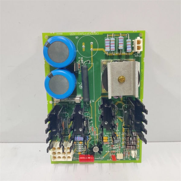
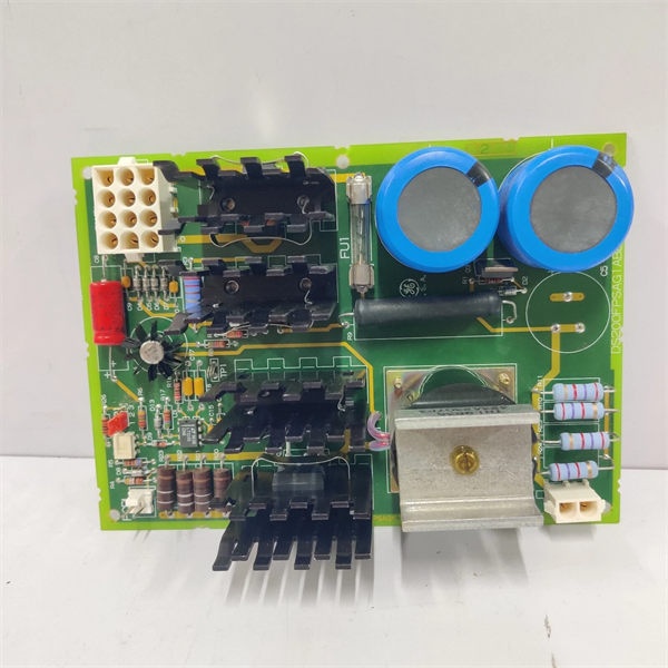
Model Number: DS200FPSAG1A
-
Manufacturer: General Electric (GE)
-
Input Voltage: 100-240 VAC, 50/60 Hz
-
Output Ratings: 24 VDC @ 5 A, 120 VAC @ 5 A (fan circuits)
-
Power: 120 W continuous, 150 W peak
-
Efficiency: > 85 % @ full load
-
Isolation: Basic insulation, 2 kV input-to-output
-
Operating Temperature: –40 °C…+70 °C
-
Cooling: Convection, no internal fan
-
Dimensions: 254 × 102 × 35 mm, 0.4 kg
-
Mounting: Mark V card-file or panel DIN-rail (clips ordered separately)
-
Protection: OVP, OCP, OTP, surge 1500 V
-
Certifications: CE, UL508, IEC 61010-1

-
Field Application & Problem Solved
In the field the biggest headache is keeping the Mark V card-file cool when the auxiliary cooling fan dies. The DS200FPSAG1A solves that by living inside the same rack and delivering both 24 VDC and 120 VAC to the fan bank. You’ll typically find it bolted behind the door on 7EA or 9F peakers—one board feeds two 120 mm fans, and if it trips the whole card-file hits 70 °C in ten minutes. Core value: it collapses a dual-voltage supply, surge suppressor, and overload relay into one 0.4 kg card you can swap while the unit is on turning gear—no external bricks, no re-wiring.
In the field the biggest headache is keeping the Mark V card-file cool when the auxiliary cooling fan dies. The DS200FPSAG1A solves that by living inside the same rack and delivering both 24 VDC and 120 VAC to the fan bank. You’ll typically find it bolted behind the door on 7EA or 9F peakers—one board feeds two 120 mm fans, and if it trips the whole card-file hits 70 °C in ten minutes. Core value: it collapses a dual-voltage supply, surge suppressor, and overload relay into one 0.4 kg card you can swap while the unit is on turning gear—no external bricks, no re-wiring.
Installation & Maintenance Pitfalls (Expert Tips)
Input Fuse Hidden on Board
The 5 A ceramic fuse is potted under the conformal coat—if you short the output the board is scrap. Always megger the fan leads before first power-up; a grounded fan cable will blow the fuse and you’ll chase a “supply fail” that can’t be field-repaired
The 5 A ceramic fuse is potted under the conformal coat—if you short the output the board is scrap. Always megger the fan leads before first power-up; a grounded fan cable will blow the fuse and you’ll chase a “supply fail” that can’t be field-repaired
.
120 VAC & 24 VDC Are Live at the Same Time
Techs assume only 24 V is present and get bit when they touch the 120 V terminal. Lock-out both circuits or meter before you work—there is no isolation switch on the card.
Techs assume only 24 V is present and get bit when they touch the 120 V terminal. Lock-out both circuits or meter before you work—there is no isolation switch on the card.
Convection Only—Don’t Block the Slots
The supply relies on rack airflow; if you leave a blank filler plate above or below the card the heat-sink hits 85 °C and the OTP trips. Keep one empty slot on each side or add a 24 VDC muffin fan if the cabinet runs hot.
The supply relies on rack airflow; if you leave a blank filler plate above or below the card the heat-sink hits 85 °C and the OTP trips. Keep one empty slot on each side or add a 24 VDC muffin fan if the cabinet runs hot.
Ignore the Output Ripple at Your Peril
Fan motors hate 2 Vpp ripple. If your battery charger float is noisy the 24 V rail will show 1.5 Vpp and the fans hum, overheat, and seize after six months. Add a 4700 µF / 50 V cap across the output terminals if ripple exceeds 500 mV.
Fan motors hate 2 Vpp ripple. If your battery charger float is noisy the 24 V rail will show 1.5 Vpp and the fans hum, overheat, and seize after six months. Add a 4700 µF / 50 V cap across the output terminals if ripple exceeds 500 mV.
Technical Deep Dive & Overview
Internally the board is a switch-mode forward converter running at 100 kHz. The primary side rectifies 100-240 VAC, feeds a MOSFET switch, and delivers 24 VDC and 120 VAC through separate secondary windings. Both outputs share a common ground tied to protective earth; opto-feedback keeps 24 V within ±2 % and a second winding gives 120 VAC for the fan bank. No fan inside—heat-sink fins are bonded to the card frame; if you block airflow the OTP halts the PWM and the supply shuts down until temperature drops below 70 °C. Swap takes five minutes: pull the card, land the input wires on the three-pole plug, snap in the output connectors, and the fans spin before you close the door.
Internally the board is a switch-mode forward converter running at 100 kHz. The primary side rectifies 100-240 VAC, feeds a MOSFET switch, and delivers 24 VDC and 120 VAC through separate secondary windings. Both outputs share a common ground tied to protective earth; opto-feedback keeps 24 V within ±2 % and a second winding gives 120 VAC for the fan bank. No fan inside—heat-sink fins are bonded to the card frame; if you block airflow the OTP halts the PWM and the supply shuts down until temperature drops below 70 °C. Swap takes five minutes: pull the card, land the input wires on the three-pole plug, snap in the output connectors, and the fans spin before you close the door.


