
Description
Hard-Numbers: Technical Specifications
- Board Dimensions: 3.25 inches high × 5 inches wide (82.6 mm × 127 mm)
- SCR Compatibility: 77mm SCR devices
- Ambient Temperature Range: 0°C to 50°C (32°F to 122°F)
- Internal Temperature Rise: +10°C above ambient inside cabinet
- Power Requirement: No onboard power supplies (powered from FGPA board)
- Diagnostic LED: C STAT (red LED for SCR blocking voltage indication)
- Fiber Optic Transmitter: U1 (gray connector, SCR voltage status transmission)
- Gate Pulse Transformer: Toroidal CT soldered to board
- Status Circuit Sensing: 10K ohm equalizer resistor current sensing
- Gate Termination: Rectified output with burden resistance for noise immunity
- Voltage Threshold Sensing: Sends signal back to FGPA when SCR voltage drop exceeds threshold
- Quantity of FHVA Connections: 5 connection points
- Assembly Type: Normal Assembly
- Parts Manual: GEI-100224
- Series Manual: GEH-6373 Innovation Series Manual
- Revision Indicator: A suffix indicates revision level (not backward compatible)
The Real-World Problem It Solves
LCI power converters require precise SCR gate control and real-time cell voltage monitoring for reliable static starter operation. The DS200FHVAG1A provides an isolated interface between the Gate Pulse Amplifier (FGPA) board and individual 77mm SCRs, enabling accurate gate drive signals while monitoring SCR blocking voltage status through fiber optic isolation.
Where you’ll typically find it:
- GE LS2100 Static Starter control cabinets
- LCI (Load Commutated Inverter) power converters for gas/steam turbines
- Static starter systems for large motor starting applications
- SCR bridge assemblies in high-power drive systems
Bottom line: Isolated gate interface board providing SCR control and cell voltage monitoring for LCI power converters.

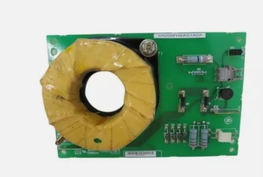
DS200FHVAG1A
Hardware Architecture & Under-the-Hood Logic
The DS200FHVAG1A serves as the critical interface point between the low-voltage control logic (FGPA board) and high-power SCR devices in the LCI power converter. Each board is dedicated to a single 77mm SCR, providing gate power isolation, cell voltage monitoring, and status feedback via fiber optic transmission. The toroidal gate pulse transformer provides galvanic isolation while withstanding electrostatic corona from high-voltage power wiring. The board monitors SCR conduction state by sensing current through the 10K ohm equalizer resistor and transmits status information back to the FGPA board through fiber optic isolation, preventing ground loops and ensuring reliable operation in high-noise environments.
Signal flow:
- Gate pulse signals received from FGPA board via toroidal pulse transformer (T1 CT)
- Gate transformer provides isolated path for gate power to SCR gate terminal (P1-1)
- Gate return current flows through SCR cathode connection (P1-2)
- Gate termination circuit rectifies transformer output and provides burden resistance for noise immunity
- SCR cell voltage monitored via equalizer resistor (E1) sensing through 10K ohm parallel resistor
- Status circuit senses SCR conduction state by detecting current in equalizer resistor
- When SCR blocking voltage present, C STAT LED illuminates indicating cell voltage
- LED brightness varies with SCR conduction angle (dimmer at higher conduction angles)
- Fiber optic transmitter U1 sends voltage status to FGPA board via gray fiber optic cable
- Equalizer current return path (E2) completes status circuit loop to SCR
- Voltage threshold detection sends signal to FGPA when SCR voltage drop exceeds setpoint
- All status signals transmitted through fiber optic isolation for noise immunity
Field Service Pitfalls: What Rookies Get Wrong
Forgetting to short P1-1 and P1-2 causes resistor burnoutNo SCR gate connected during testing. I’ve seen technicians leaving the FHVA board powered without shorting pins P1-1 and P1-2, causing resistors R1 and R2 to overheat and fail.
- Field Rule: Always short P1-1 and P1-2 together when the board is powered without an SCR gate connected. This provides a current path and prevents resistor overheating. Never leave the gate output open-circuited during testing. Document this procedure in your test setup. Verify resistor temperatures during initial power-up—if hot, check the shorting connection immediately.
Leaving fiber optic connector uncovered causes lens contaminationDust accumulates on unprotected fiber lenses. I’ve seen technicians leaving the U1 fiber optic connector uncovered for hours, requiring lens cleaning and causing intermittent status signals.
- Field Rule: Insert the rubber plug into U1 whenever the fiber optic cable is disconnected for more than one hour. Even dusty environments can contaminate the lens within an hour of exposure. Store the rubber plug in a clean location—never lose it. Clean the lens with compressed air before reconnection. Document fiber disconnect times in your maintenance log. Never operate without lens protection during extended outages.
Misinterpreting C STAT LED dimming as fault conditionLED brightness varies with conduction angle. I’ve seen technicians diagnosing faulty boards because the C STAT LED dims during normal operation, not realizing this indicates increased SCR conduction angle.
- Field Rule: Understand LED behavior before troubleshooting. C STAT LED should be visible when bridge power is activated, indicating blocking voltage presence. LED dimming is normal as SCR conduction angle increases—this is expected behavior, not a fault. Compare LED brightness across all FHVA boards in the converter—significant variation may indicate a problem. Document LED brightness patterns during normal operation for future reference.
Incorrect CT wire routing through toroidal transformer reduces gate pulse strengthPrimary wire not centered in CT window. I’ve seen technicians routing the primary wire off-center in the T1 toroidal transformer, reducing coupling efficiency and causing weak gate drive.
- Field Rule: Center the primary wire in the T1 CT window for optimal coupling and corona avoidance. The single-turn primary wire from the board must pass through the center of the toroidal transformer. Use the board hole provided to position the wire correctly. Verify gate pulse strength with an oscilloscope during commissioning. Never route the primary wire near the CT edge—this reduces effectiveness and increases corona risk.
Mixing up gate (P1-1) and cathode (P1-2) connections prevents SCR firingRed/White wire pair polarity confusion. I’ve seen technicians connecting the red conductor to P1-1 and white to P1-2, reversing the gate polarity and preventing SCR turn-on.
- Field Rule: Follow the color code strictly. P1-1 (Gate) connects to the white conductor of the Red/White pair. P1-2 (Cathode) connects to the red conductor of the Red/White pair. Label wires clearly during installation. Verify polarity with a multimeter before connecting to SCR. Never rely on memory—document the color code in your wiring diagrams. Reversed polarity causes SCR firing failures.
Ignoring equalizer resistor (E1/E2) connections causes erratic status sensingMissing stab joiner connections. I’ve seen technicians forgetting to connect E1 (equalizer resistor) and E2 (current return path), causing the status circuit to fail and send incorrect SCR status to the FGPA.
- Field Rule: Verify both E1 and E2 connections are secure. E1 connects the equalizer resistor (stab joiner), and E2 provides the equalizer current return path. Both connections are critical for accurate SCR status sensing. Test status circuit operation after installation by monitoring C STAT LED behavior. Document E1/E2 connection points in your as-built drawings. Never operate with missing equalizer connections.
Failing to clean fiber optic lenses before reconnection causes signal lossDust on fiber ends blocks light transmission. I’ve seen technicians reconnecting fiber cables without cleaning the lenses, causing intermittent status signals and false SCR fault indications.
- Field Rule: Always clean fiber optic lenses with compressed air before reconnection. Inspect lenses for contamination—clean if necessary. Use isopropyl alcohol and lint-free cloth for stubborn contamination. Never touch fiber ends with bare fingers. Verify fiber continuity after reconnection using the FGPA board diagnostics. Document lens cleaning in your maintenance procedures.
Over-torquing terminal connections damages board terminalsExcessive force breaks solder joints. I’ve seen technicians using power tools on P1 and E terminals, stripping threads and damaging internal board connections.
- Field Rule: Use a manual screwdriver for all terminal connections. Apply gentle torque—just enough to secure the wire without deforming the terminal. For high-vibration applications, use locking washers or thread-locking compound. Never use power drivers on FHVA board terminals. Inspect terminals for damage during routine maintenance. Document torque specifications in your installation procedures.
Missing the A revision compatibility assumption causes replacement errorsA suffix indicates non-backward compatibility. I’ve seen technicians replacing an FHVA with a base revision board, expecting it to work with the A revision system configuration.
- Field Rule: Always match the exact part number including revision letters. The A suffix on DS200FHVAG1A indicates a revision level that is not backward compatible with earlier revisions. Cross-reference the replacement part number with the original board label. Verify compatibility with the LCI system configuration before installation. Never assume revision compatibility—check the parts manual GEI-100224.
Improper board positioning causes corona discharge in high-voltage environmentBoard too close to high-voltage conductors. I’ve seen technicians installing FHVA boards near high-voltage bus bars without adequate clearance, causing corona discharge and board damage.
- Field Rule: Maintain proper clearance from high-voltage conductors. The FHVA board is designed for high-voltage environments but requires adequate spacing to prevent corona. Follow the LCI cabinet layout drawings for board positioning. Use non-conductive mounting hardware if required. Document board location in cabinet drawings. Never install the board in high-field-strength areas without consulting GE guidelines.
Forgetting fiber optic transmitter damage during board handlingESD and mechanical stress damage fiber components. I’ve seen technicians handling the board without ESD protection, damaging the sensitive fiber optic transmitter U1 and causing permanent signal loss.
- Field Rule: Always use ESD protection when handling FHVA boards. Ground yourself before touching any board components. Hold the board by the edges only—never touch components or connectors. Store boards in anti-static packaging when not installed. Inspect the fiber optic transmitter for damage before installation. Never apply mechanical stress to the U1 connector. Document ESD procedures in your maintenance training.
Commercial Availability & Pricing Note
Please note: The listed price is for reference only and is not binding. Final pricing and terms are subject to negotiation based on current market conditions and availability.


