
Description
Key Technical Specifications
-
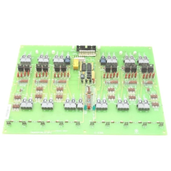
Model Number: DS200FCRLG1AFC
-
Manufacturer: General Electric
-
Function: SCR firing-circuit & relay logic driver
-
Outputs: 27 bayonet-type isolated firing pulses
-
Jumpers: 27 berg jumpers for phase angle, pulse width, enable logic
-
Connectors: 1 × 34-pin, 1 × 9-pin D-Sub I/O; multiple bayonet HV ports
-
Signal Type: High-speed, regulated 5–24 V pulses (configurable per system)
-
Isolation: 1500 Vdc channel-to-ground
-
Operating Temperature: 0 °C – 60 °C
-
Storage Temperature: –40 °C – 85 °C
-
Board Size: ≈ 11 × 8 in (279 × 203 mm)
-
Weight: ≈ 1.2 kg
-
Construction: Normal conformal coat, non-repairable epoxy-sealed traces

DS200FCRLG1AFC
Field Application & Problem Solved
In a 7EA peaker the static-start SCR bridge needs 27 isolated gate pulses that swing from –15 V (quench) to +15 V (fire) in < 2 µs. This board lives in the high-voltage cabinet, receives 5 V logic edges from the SDCC, and shoots them down bayonet lines to each SCR’s gate-quench unit. When a lightning hit blows an output trace, the epoxy-sealed design limits damage to one channel—you swap the whole card, retorque the bayonets, and the turbine is back to crank speed in five minutes. No re-download, no re-cal—just bolt-in and go.
In a 7EA peaker the static-start SCR bridge needs 27 isolated gate pulses that swing from –15 V (quench) to +15 V (fire) in < 2 µs. This board lives in the high-voltage cabinet, receives 5 V logic edges from the SDCC, and shoots them down bayonet lines to each SCR’s gate-quench unit. When a lightning hit blows an output trace, the epoxy-sealed design limits damage to one channel—you swap the whole card, retorque the bayonets, and the turbine is back to crank speed in five minutes. No re-download, no re-cal—just bolt-in and go.
Installation & Maintenance Pitfalls (Expert Tips)
Jumpers define the pulse personality
Factory default is 60° phase retard. If your system runs 120° soft-start and you don’t move JP1-JP6, the bridge fires early, pulls 1500 A, and pops the mains fuse. Match the jumper table taped inside the cabinet door before you land the HV lines.
Jumpers define the pulse personality
Factory default is 60° phase retard. If your system runs 120° soft-start and you don’t move JP1-JP6, the bridge fires early, pulls 1500 A, and pops the mains fuse. Match the jumper table taped inside the cabinet door before you land the HV lines.
Bayonet connectors must click twice
These carry 15 V gate at 3 A peak. A half-latch adds 2 Ω resistance; the SCR sees 12 mA instead of 150 and misfires. Twist until you feel the second detent, then tug-test.
These carry 15 V gate at 3 A peak. A half-latch adds 2 Ω resistance; the SCR sees 12 mA instead of 150 and misfires. Twist until you feel the second detent, then tug-test.
Board is live at bus potential
The heat-spreader plane floats at cathode potential. Bolt it to the cabinet while the bridge is hot and you’ll strike an arc across the mounting hole. Always rack the DC breaker before you swap the card.
The heat-spreader plane floats at cathode potential. Bolt it to the cabinet while the bridge is hot and you’ll strike an arc across the mounting hole. Always rack the DC breaker before you swap the card.
Non-repairable means exactly that
Epoxy-potted traces won’t take a solder iron. If a bayonet pad lifts, order a new board—attempting repair voids the UL listing and you’ll fight the same fault next month
Epoxy-potted traces won’t take a solder iron. If a bayonet pad lifts, order a new board—attempting repair voids the UL listing and you’ll fight the same fault next month
.
Technical Deep Dive & Overview
Internally the card is a passive pulse amplifier matrix. 27 HCPL-4504 opto-couplers convert 5 V CMOS from the SDCC into 15 V gate pulses; each output hits a 10 Ω gate resistor inside the bayonet shell. Because everything is hardware, you can hot-swap with the bridge powered—pull the old card, move bayonets one-for-one, snap the 34-pin and 9-pin connectors, and the SDCC re-syncs gate pulses inside 50 ms. No processor, no firmware—just copper, caps, and light.
Internally the card is a passive pulse amplifier matrix. 27 HCPL-4504 opto-couplers convert 5 V CMOS from the SDCC into 15 V gate pulses; each output hits a 10 Ω gate resistor inside the bayonet shell. Because everything is hardware, you can hot-swap with the bridge powered—pull the old card, move bayonets one-for-one, snap the 34-pin and 9-pin connectors, and the SDCC re-syncs gate pulses inside 50 ms. No processor, no firmware—just copper, caps, and light.


