
Description
Hard-Numbers: Technical Specifications
-
Function: Gate Distribution and Status Card (FCGD) for LCI control
-
Bridge Interface: 6-pulse phase-controlled non-reversing bridge
-
Channels: 12 channels (-8 mV to +45 mV signal span)
-
Processor Interface: DSPC (Digital Signal Processing Card) via VME backplane
-
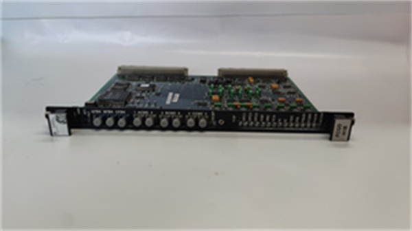
Gate Drive: Fiber optic firing signal transmitters (up to 6)
-
Feedback: Multiplexed cell status from bridge legs, voltage, current, frequency
-
Power Supply: 24 VDC
-
Operating Temperature: -30°C to +65°C (-22°F to 149°F)
-
Storage Temperature: -55°C to +85°C
-
Humidity: 5% to 95% non-condensing
-
Dimensions: 9.2″ × 6.3″ (233.68 × 159.44 mm), 6U VME form factor
-
Weight: 0.45 kg (1 lb)
-
PCB Coating: Conformal coating for environmental protection
-
LED Indicators: IMOK (system heartbeat/status)
-
Manual: GEI-100221

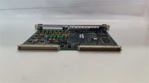
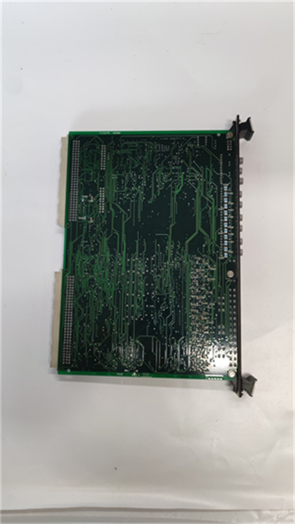
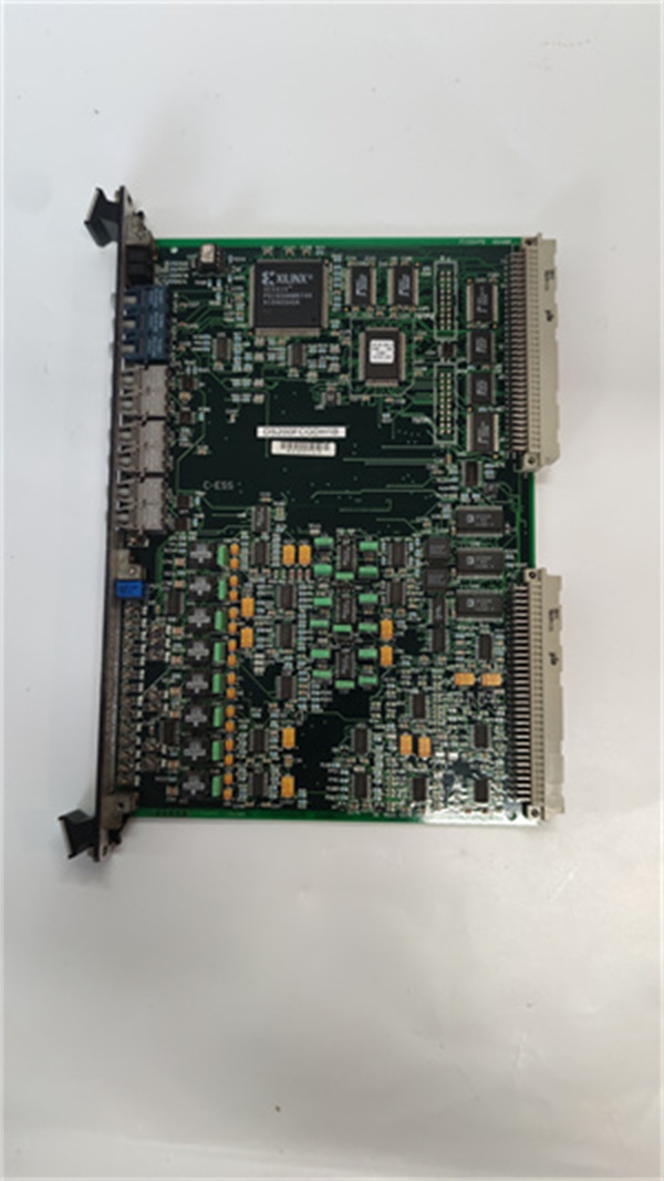
GE DS200FCGDH1B
The Real-World Problem It Solves
You know the scenario: a 6-pulse thyristor bridge in an LCI drive where the firing pulses need precise timing (microsecond accuracy) to commutate current between SCRs without shoot-through, while the control processor sits safely on a VME backplane away from the high voltage. The DS200FCGDH1B bridges that gap—it receives SCR firing commands from the DSPC processor via VME, converts them to fiber optic gate pulses for the thyristors, then multiplexes status feedback (voltage, current, commutation timing) back to the processor. Without this board, your LCI drive can’t fire SCRs, can’t commutate, and can’t control the DC link. It’s the critical interface between the digital control world and the analog power electronics world.
Where you’ll typically find it:
-
EX2100 excitation systems for generator field control in combined-cycle plants
-
LCI variable frequency drives for large induction motors in compressor stations
-
Static starter systems for gas turbines (LCI starter)
Bottom line: It translates digital firing commands from the VME processor into precise gate pulses for high-power thyristors, while providing isolation and feedback to protect the control system from kilovolt-level power electronics.
Hardware Architecture & Under-the-Hood Logic
The DS200FCGDH1B is not a general-purpose I/O board—it’s a specialized power electronics interface. It sits in a 6U VME slot and communicates with the DSPC (Digital Signal Processing Card) via the VME backplane. On the power side, it connects to the thyristor bridge through fiber optic cables (for gate firing) and status feedback lines. The board contains high-speed logic for decoding firing commands, generating precise gate pulses, and multiplexing bridge status signals.
Signal flow and control logic:
-
Command Reception: The DSPC sends SCR firing commands via VME bus writes to the FCGD’s registers—timing, phase, and duration data for each thyristor
-
Clock Synchronization: An onboard 16-bit system clock (0FFFFH rollover) timestamps all firing commands and feedback to ensure microsecond-level synchronization with the AC line
-
Gate Pulse Generation: The board decodes firing commands and generates fiber optic pulses to trigger the SCR gate drivers—six pulses for a 6-pulse bridge, properly sequenced for 120° conduction
-
Status Multiplexing: The board receives multiplexed status from each bridge leg (voltage, current, commutation success) via fiber optics from FGPA boards, then demultiplexes and scales this data
-
Feedback to DSPC: Processed feedback (voltage, frequency, current, ground fault, overcurrent) transmits back to the DSPC via VME bus for closed-loop control and protection

GE DS200FCGDH1B
Field Service Pitfalls: What Rookies Get Wrong
Treating This Like a Standard VME I/O Card Rookies see “VME board” and assume this is a generic digital I/O module they can test with a multimeter. It’s not. The DS200FCGDH1B handles high-voltage isolation, fiber optic communication, and microsecond-level timing. You can’t troubleshoot it with a simple continuity tester—you need fiber optic test equipment and oscilloscopes rated for the voltage class.
Field Rule: Never probe the fiber optic connectors with metal tools or your fingers—oil and scratches destroy the optical path. Use only approved fiber cleaning kits. Verify the IMOK LED is solid green before declaring the board healthy; flashing or off indicates clock or communication faults. If the LCI drive won’t commutate, check the fiber optic cables first—90% of FCGD “failures” are actually broken fibers or dirty connectors.
Confusing FCGD with DSPC The FCGD (DS200FCGDH1B) and DSPC (DS200DSPCx) work as a pair but are not interchangeable. The DSPC is the VME processor; the FCGD is the gate driver interface. Rookies replace the wrong board and wonder why the fault persists.
Quick Fix: If you have “Gate Drive Fault” or “Commutation Failure” alarms, the FCGD is suspect. If you have “Processor Fault” or “VME Bus Error,” the DSPC is suspect. The FCGD has no microprocessor—it’s all FPGA and discrete logic. If the IMOK LED is off, the board isn’t getting clock or reset from the DSPC. Check the DSPC first before replacing the FCGD.
Ignoring the Fiber Optic Bend Radius The fiber optic cables connecting the FCGD to the thyristor gate drivers have minimum bend radius requirements (typically 1.5 inches). Rookies route them with sharp bends to make them fit in crowded cabinets, causing attenuation or breakage.
Field Rule: Verify fiber optic cables have gentle bends (radius >40mm) and aren’t pinched by cabinet doors. Use strain relief at both ends—vibration from the turbine will work loose unprotected connectors. If you see “Intermittent Gate” alarms that clear when you wiggle the cabinet wiring, you’ve got a fiber integrity problem. Replace the fiber cable, not the FCGD board.
Forgetting the 24VDC Isolation The FCGD requires 24VDC power, but this must be isolated from the VME backplane +5V. Rookies share grounds between the 24V field power and the VME logic ground, creating ground loops that cause erratic firing or DSPC resets.
Field Rule: Use an isolated 24VDC power supply for the FCGD. Verify with a multimeter that there’s no continuity between the 24V return and the VME backplane ground. If you measure voltage between them, you’ve got a ground loop that will cause intermittent commutation failures. The FCGD has internal isolation, but external wiring mistakes can defeat it.


