
Description
Key Technical Specifications
-
Model Number: DS200EXPSG1A
-
Manufacturer: General Electric (GE)
-
Input Supply: 400-480 VAC three-phase (cabinet bus) OR 125 VDC station battery
-
Output Rails:
-
+5 V: 40 A (logic)
-
±12 V: 3 A (analog)
-
+24 V: 10 A (relays / solenoids)
-
+15 V: 2 A (IGBT gate drivers)
-
-
Efficiency: ≥ 92 % @ 50 % load; active PFC + sync rectifier
-
Battery Charge: JP1 jumper selects 0.1 C or 0.2 C limit; < 5 A inrush on black-start
-
Protection: 3 × fast-blow fuses (F1/F2/F3), OVP, OCP, OTP; auto-shutdown with D-Sub fault report
-
Status & Test: Green LED “Power OK”, reset push-button, multiple TPxx test points for DMM
-
Connectors: 3 × 9-pin D-Sub (monitor), 2 × bolt terminals (input bus), 1 × 40-pin flat cable (back-plane)
-
Operating Temperature: –40 °C…+70 °C; conformal-coated, 1000 h salt-spray rated
-
Dimensions / Weight: 220 × 160 × 80 mm, 2.5 kg
- MTBF: > 250 000 h; CE, UL, RoHS listed

Field Application & Problem Solved
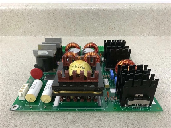
In the field the biggest pain is stuffing four separate power supplies into a Mark V cabinet—one for 5 V logic, another for ±12 V analog, a 24 V brick for relays, and a 15 V module for IGBT drivers. The DS200EXPSG1A replaces all of them with a single 2.5 kg card. You’ll typically find it bolted behind the door on 7EA or 9F peakers: one board feeds the whole rack, reports fuse and temperature status over a D-Sub, and still gives you online test points so you can meter each rail without opening the cabinet. Core value: it collapses four supplies, a battery charger, and a fault annunciator into one plug-in card that saves 30 % panel space and cuts MTTR in half.
In the field the biggest pain is stuffing four separate power supplies into a Mark V cabinet—one for 5 V logic, another for ±12 V analog, a 24 V brick for relays, and a 15 V module for IGBT drivers. The DS200EXPSG1A replaces all of them with a single 2.5 kg card. You’ll typically find it bolted behind the door on 7EA or 9F peakers: one board feeds the whole rack, reports fuse and temperature status over a D-Sub, and still gives you online test points so you can meter each rail without opening the cabinet. Core value: it collapses four supplies, a battery charger, and a fault annunciator into one plug-in card that saves 30 % panel space and cuts MTTR in half.
Installation & Maintenance Pitfalls (Expert Tips)
Input Fuse Is Potted—Don’t Blow It
F1/F2/F3 are buried under conformal coat; short the output and the card is scrap. Always megger the load cables before first power-up; a grounded 24 V fan lead will blow the fuse and you’ll chase a “supply fail” that can’t be field-repaired.
F1/F2/F3 are buried under conformal coat; short the output and the card is scrap. Always megger the load cables before first power-up; a grounded 24 V fan lead will blow the fuse and you’ll chase a “supply fail” that can’t be field-repaired.
Battery Charge Jumper Sets Inrush
JP1 at 0.2 C will slam 25 A into a flat 125 V battery; set it to 0.1 C for black-start or you’ll trip the station DC breaker and the turbine will never crank.
JP1 at 0.2 C will slam 25 A into a flat 125 V battery; set it to 0.1 C for black-start or you’ll trip the station DC breaker and the turbine will never crank.
D-Sub Status Pins Are Live at 28 V
The 9-pin monitor connector floats at logic potential; if you scope it with a grounded lead you’ll short the fault line and create a false “supply OK.” Use a differential probe or pull the connector first.
The 9-pin monitor connector floats at logic potential; if you scope it with a grounded lead you’ll short the fault line and create a false “supply OK.” Use a differential probe or pull the connector first.
Ripple > 500 mV Kills IGBT Drivers
The 15 V rail feeds gate drivers—2 Vpp ripple will make the IGBTs switch late and overheat. If your battery charger is noisy add a 4700 µF / 50 V cap across the 15 V output or you’ll discover the weakness during the next load rejection.
The 15 V rail feeds gate drivers—2 Vpp ripple will make the IGBTs switch late and overheat. If your battery charger is noisy add a 4700 µF / 50 V cap across the 15 V output or you’ll discover the weakness during the next load rejection.
Technical Deep Dive & Overview
Internally the card is a forward-converter SMPS running at 100 kHz. Active PFC on the 480 V input gives > 0.9 power factor; synchronous rectifiers on each secondary hold efficiency above 92 %. Opto-couplers report fuse status and temperature to the DSP; lose any rail and the Mark V throws “EXPS FAIL” within 50 ms. No fan inside—heat-sink fins are bonded to the card frame; block airflow and the OTP halts the PWM until temperature drops below 70 °C. Swap takes five minutes: pull the card, land the input lugs, plug the 40-pin ribbon, and all four rails come up in sequence—no external sequencing hardware required.
Internally the card is a forward-converter SMPS running at 100 kHz. Active PFC on the 480 V input gives > 0.9 power factor; synchronous rectifiers on each secondary hold efficiency above 92 %. Opto-couplers report fuse status and temperature to the DSP; lose any rail and the Mark V throws “EXPS FAIL” within 50 ms. No fan inside—heat-sink fins are bonded to the card frame; block airflow and the OTP halts the PWM until temperature drops below 70 °C. Swap takes five minutes: pull the card, land the input lugs, plug the 40-pin ribbon, and all four rails come up in sequence—no external sequencing hardware required.


