
Description
Hard-Numbers: Technical Specifications
- Auxiliary Boards: 7 × DS200DSPA display modules
- LED Displays: 70 total digits (10 digits per auxiliary board)
- LED Indicators: 32 LEDs arranged in 8 rows of 4
- Communication: ARCNET connectivity for system integration
- Key Components: FPGAs, oscillation chips, EEPROM for logic
- Voltage Protection: Capacitors, resistors, diodes for voltage limiting
- PCB Coating: Normal conformal coating
- Interconnect: Brass pin connectors between main board and auxiliary boards
- Functional Revisions: A (primary), C (secondary), C (artwork)
- Compatibility: Mark V Speedtronic system architecture
- Mounting: Cabinet door or rack-mounted for operator access
- Operating Temperature: 0°C to 60°C (typical Mark V range)
- Data Path: Real-time turbine parameters via ARCNET

GE DS200DDTBG2A
The Real-World Problem It Solves
Operators need real-time visibility of turbine parameters without relying solely on remote HMI stations. The DS200DMCAG1AJD puts critical data directly in the control cabinet, enabling rapid diagnosis and manual intervention during startup, shutdown, and fault conditions.
Where you’ll typically find it:
- GE gas and steam turbine control cabinets
- Mark V control system operator interface panels
- Exciter control system displays (EX2000 integration)
- Auxiliary drive control panels requiring local indication
Bottom line: Local visual data interface for real-time turbine parameter monitoring and operator decision support.
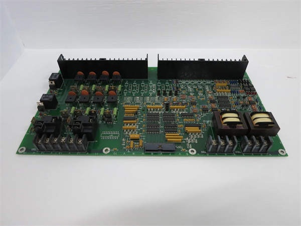
Hardware Architecture & Under-the-Hood Logic
The DS200DMCAG1AJD serves as the main display interface for the Mark V turbine control system. It consists of a primary board populated with voltage protection components, FPGAs, and EEPROM logic. Seven DS200DSPA auxiliary boards connect via brass pin headers, each providing a 10-digit LED display. The board communicates with the Mark V control processors via ARCNET, receiving real-time turbine data and displaying it on the LED arrays.
Signal flow:
- Power supplied via backplane connection (5 VDC typical)
- Control processors send turbine data via ARCNET network
- FPGA on main board receives and processes data packets
- EEPROM stores display configuration and mapping parameters
- Data routed to auxiliary DS200DSPA boards via brass pin connectors
- Each auxiliary board drives its 10-digit LED display segment
- LED indicators (32 total) updated based on system status
- Keyboard inputs (if present) routed back to control processors
- Display refresh rate synchronized with control processor scan
- Voltage protection circuits suppress transients from backplane
GE DS200DDTBG2A
Field Service Pitfalls: What Rookies Get Wrong
Mishandling DS200DSPA auxiliary boards breaks brass pin connectorsThe auxiliary boards are fragile. I’ve seen technicians prying them off without releasing the locking mechanism, bending brass pins and destroying the interconnect.
- Field Rule: Never force auxiliary boards. Release the locking mechanism (if equipped) before removal. Pull straight up—no rocking or twisting. Inspect brass pins for straightness before reinstalling. If pins are bent, use needle-nose pliers to gently realign—never reuse damaged boards. Document auxiliary board positions during removal—they may not be identical.
Forgetting to document LED display mappings causes confusion after replacementEach 10-digit display shows different parameters. I’ve seen technicians replacing the board without noting which display shows MW, KV, or MVAR, leaving operators guessing during startup.
- Field Rule: Photograph all displays showing normal operation before removal. Document which auxiliary board position corresponds to which parameter group. Map displays 1-7 to their specific turbine parameters. Verify each display shows correct data after replacement. Never assume default configuration matches your application—parameters are application-specific.
Ignoring EEPROM configuration loss causes blank displaysConfiguration stored in EEPROM. I’ve seen technicians swapping boards without transferring EEPROM settings, resulting in blank or garbled displays after power-up.
- Field Rule: Verify EEPROM configuration matches application before removal. If replacing the main board, transfer EEPROM or reconfigure using toolbox software. Test all displays after power-up—blank displays indicate missing configuration. Document EEPROM settings or backup configuration via toolbox. Never assume a new board comes preconfigured for your turbine.
ARCNET communication failure displays outdated dataNetwork issues freeze displays. I’ve seen technicians trusting frozen displays during a trip, not realizing the data is 10 minutes old.
- Field Rule: Verify ARCNET communication status before relying on displays. Check network LEDs on the board—should blink periodically. Test communication by changing a parameter and verifying display updates. If communication fails, troubleshoot network before diagnosing turbine issues. Never assume frozen displays equal real-time data.
Over-tightening mounting screws cracks the PCB or cabinet doorExcessive torque fractures the board. I’ve seen technicians using power drivers to mount display boards on cabinet doors, cracking the PCB and stripping door threads.
- Field Rule: Mounting screws should be finger-tight plus 1/4 turn maximum. Use appropriate washers to distribute load. Never exceed manufacturer torque specification—typically under 10 in-lbs for display boards. Verify cabinet door can support the board weight without warping. Re-torque after initial heat cycle (24 hours) if specified.
Touching LED segments during cleaning causes permanent damageFinger oils and pressure degrade segments. I’ve seen technicians wiping displays with bare hands and excessive force, causing segments to dim or fail permanently.
- Field Rule: Never touch LED displays with bare fingers. Use lint-free cloth dampened with isopropyl alcohol for cleaning. Apply minimal pressure—LED segments are not glass. Clean from cabinet interior only—never open the display housing. Document any segment damage during inspection—failed segments indicate thermal or mechanical stress.
Confusing DS200DMCAG1AJD with DS200DMCAG1A causes compatibility issuesRevisions matter. I’ve seen technicians installing a DMCA board without the JD suffix, expecting it to work with DS200DSPA auxiliary boards, discovering incompatibility during commissioning.
- Field Rule: Verify the exact part number includes the JD suffix for DS200DSPA compatibility. Earlier revisions (DMCA, DMCA-A) may not support all auxiliary board features. Cross-reference the manual for revision-specific compatibility. Test all auxiliary boards after installation—mismatched revisions may not display data correctly. Never assume revision compatibility without verification.
Hot-swapping auxiliary boards while powered damages FPGAsLive insertion causes voltage spikes. I’ve seen technicians adding or removing DS200DSPA boards while the main board is powered, blowing FPGA outputs and blanking displays.
- Field Rule: De-energize the main board before installing or removing auxiliary boards. Follow proper lockout/tagout procedures. Verify zero voltage on brass pin connectors with a multimeter. Never hot-swap any component—voltage transients will damage FPGAs and display drivers. Document LOTO procedures for display board maintenance.
Ignoring voltage protection component degradation causes intermittent failuresCapacitors and diodes age. I’ve seen technicians ignoring bulging capacitors on the main board, resulting in intermittent display flickering and eventual failure.
- Field Rule: Inspect voltage protection components during routine maintenance. Check electrolytic capacitors for bulging, leaking, or venting. Test diodes with a multimeter—should show proper forward voltage drop. Replace any degraded components immediately. Document component condition—thermal stress degrades protection over time. Never operate with known degraded protection circuits.
Improper cable routing blocks airflow and causes overheatingCables draped over the board trap heat. I’ve seen technicians routing ribbon cables across auxiliary boards, causing thermal shutdown and segment failure.
- Field Rule: Route all cables away from display board surface. Maintain minimum 1-inch clearance above and around auxiliary boards. Never bundle signal cables with power cables near the display. Use cable ties to secure cables to cabinet sidewalls. Document cable routing—improper airflow reduces LED lifespan. Verify cabinet temperature stays below 50°C during operation.
Commercial Availability & Pricing Note
Please note: The listed price is for reference only and is not binding. Final pricing and terms are subject to negotiation based on current market conditions and availability.


