
Description
Hard-Numbers: Technical Specifications
- LED Count: 32 status LEDs (labeled DS1-DS32)
- Display Count: 21 four-character alphanumeric displays
- Character Type: Sixteen-segment per character
- Connection Strip: 40-pin rear connector (3PL)
- Jumpers: 1 Berg-type manually movable jumper
- Operational Voltage: 5 VDC (via backplane)
- Operating Temperature: 0°C to 60°C
- Storage Temperature: -55°C to +85°C
- Relative Humidity: 5% to 95% non-condensing
- PCB Coating: Normal conformal coating
- Dimensions: 38 cm × 21.5 cm × 4.5 cm
- Weight: 0.96-1.22 kg
- Revision Level: 3 revisions supported (AAA = third revision)
- Mounting: Four corner screw holes with insulated mounting rings

GE DS200DCFBG1BLC
The Real-World Problem It Solves
Operators need immediate visual access to drive status, alarms, and diagnostic data without running to a remote HMI station. The DS200KLDCG1AAA puts the information right on the cabinet door, eliminating blind spots during startup and troubleshooting.
Where you’ll typically find it:
- GE gas and steam turbine control cabinets
- Mark V drive control racks with operator access doors
- Static starter (LCI) control panels
- Industrial motor drive systems requiring local indication
Bottom line: Local operator interface with visual status indication for Mark V turbine control systems.
Hardware Architecture & Under-the-Hood Logic
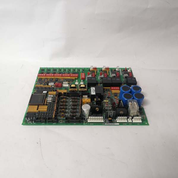
The DS200KLDCG1AAA is a passive display board that receives data from the Mark V control processor via the 40-pin backplane connector. It does not process signals—it drives LEDs and displays based on commands from the control rack. The board contains voltage-limiting components (resistors, capacitors, diodes) to protect the display circuitry from backplane transients.
Signal flow:
- Power supplied via 40-pin backplane connector (5 VDC and ground)
- Display data received from Mark V control processor through backplane
- LED drivers illuminate individual LEDs based on processor commands
- Sixteen-segment display controllers drive alphanumeric characters
- Jumper position read by processor for configuration identification
- Status information refreshed continuously by control processor
- No onboard processing—all logic handled by Mark V controller
- Visual output displayed to operator via front-panel LEDs and displays
GE DS200DCFBG1BLC
Field Service Pitfalls: What Rookies Get Wrong
Moving the wrong jumper position renders the board inoperableSome jumpers are factory-only. I’ve seen technicians repositioning the board jumper to “try different settings,” causing the processor to misidentify the board configuration.
- Field Rule: Document jumper positions before removal. The single jumper on this board typically covers pins 1-2 or 2-3—changing it alters board behavior. Factory jumpers are for manufacturing test only—do not reposition them. Verify jumper settings match the original board during replacement. Refer to GEI-100219 manual for correct jumper configuration per your application.
Improper cable routing blocks cooling airflow and causes EMI issuesCables routed over the board trap heat and induce noise. I’ve seen technicians drape ribbon cables across the display area, causing erratic LED behavior and overheating components.
- Field Rule: Route cables away from the board surface. Maintain minimum 2-inch clearance above displays for airflow. Never bundle signal cables with power cables near the display board. Use cable ties to secure cables to cabinet sidewalls, not across the board. Document cable routing during removal—restore identical routing on reinstall.
Over-tightening mounting screws cracks the PCB or damages standoffsExcessive torque fractures the board. I’ve seen technicians using power drivers to mount the board, stripping the insulated mounting rings and cracking the PCB around the screw holes.
- Field Rule: Mounting screws should be finger-tight plus 1/8 turn. Never use power tools—hand-tighten only. The four corner holes have insulated rings to prevent shorts—do not replace with standard metal screws. Verify all standoffs are present before mounting. Torque to manufacturer specification if specified in manual—typically under 5 in-lbs for PCB mounting.
Blind-inserting the 40-pin connector misaligns pins and damages the boardThe connector is not keyed on all revisions. I’ve seen technicians forcing the connector offset by one pin, bending pins and blowing display drivers.
- Field Rule: Verify Pin 1 alignment before insertion. Pin 1 is typically marked with a red stripe on the ribbon cable and a square pad or marking on the PCB connector. Align Pin 1 on cable with Pin 1 on board. Inspect pins for straightness before insertion—never force a misaligned connector. Test all LEDs and displays after installation to verify proper connection.
Ignoring static discharge protection during handling kills display driversLED drivers are ESD-sensitive. I’ve seen technicians pulling the board from static bags without grounding, blowing display segments immediately upon power-up.
- Field Rule: Always ground yourself before handling the board. Use an anti-static wrist strap connected to cabinet ground. Handle the board by the edges—never touch component side. Store in anti-static bag when not installed. Ground the cabinet before board installation. Never place the board on conductive surfaces (metal tabletops).
Confusing DS200KLDCG1AAA with DS200KLDCG1 causes configuration mismatchRevisions matter. I’ve seen technicians installing a G1 board in place of a G1AAA, expecting backward compatibility without verifying functionality.
- Field Rule: Verify the exact part number matches the original. DS200KLDCG1AAA is the third revision—earlier revisions (G1, G1A) have limited backward compatibility. Check the manual for revision-specific functionality differences. Test all displays and LEDs after replacement—mismatched revisions may show incorrect data or fail to display某些 segments. Document the original part number before ordering replacements.
Not labeling connector positions during removal causes miswiring on reinstallThe 40-pin connector and key wiring are not labeled. I’ve seen technicians removing all cables without documentation, then guessing during reinstall.
- Field Rule: Label every cable and connector position before removal. Use tape tags or a camera to document orientation. The board may have multiple connection points—document each one. Verify cable keying matches connector orientation. Never rely on memory—always document. Reference the manual for correct pinout if uncertainty exists.
Operating beyond temperature range burns out LED segmentsHigh ambient degrades LEDs faster. I’ve seen boards installed in cabinets exceeding 60°C ambient, resulting in dim displays and failed segments within months.
- Field Rule: Verify cabinet temperature stays below 45°C for long-term reliability. Install cabinet cooling fans if temperature exceeds 50°C during normal operation. Monitor LED brightness during startup—dimming indicates thermal stress. Replace boards showing thermal damage and address root cause (cooling, ventilation). Never install display boards in high-heat zones near power converters.
Forgotten to document display mappings during replacement causes operator confusionDisplay layout varies by application. I’ve seen technicians replacing the board without noting which display shows what data, leaving operators guessing during startup.
- Field Rule: Document which display corresponds to which parameter before removal. Photograph the display showing normal operation. Map each 4-character display to its function during commissioning. Provide operators with updated display maps after board replacement. Never assume the new board will display data identically—verify each display shows correct information after startup.
Touching the display segments with fingers causes oil contamination and reduced visibilityFinger oils degrade display clarity. I’ve seen technicians pointing at display segments during troubleshooting, leaving fingerprints that attract dust and obscure readings.
- Field Rule: Never touch the LED or display surfaces with bare fingers. Use a non-conductive pointer for troubleshooting. Clean displays with isopropyl alcohol and lint-free cloth if contaminated. Install a protective polycarbonate cover if the board is in a high-traffic area. Train operators to use keypads, not displays, for interaction. Document any display damage during handover.
Commercial Availability & Pricing Note
Please note: The listed price is for reference only and is not binding. Final pricing and terms are subject to negotiation based on current market conditions and availability.


