
Description
Hard-Numbers: Technical Specifications
- Power Supply: 24-32 VDC (28 VDC nominal via ADMA)
- Power Consumption: < 8 W
- Analog Outputs: 4 channels, 0-10 VDC, 12-bit resolution (TP14-TP17)
- 4-20 mA Outputs: 2 channels with current source buffers (simultaneous with voltage outputs)
- Digital Inputs: 8 channels, optically isolated, 24-250 VDC/24-230 VAC (TP17-TP25)
- Relay Outputs: 16 Form-C relays, 2 A @ 240 VAC or 10 A @ 30 VDC
- High-Voltage AC Inputs: 2 isolated inputs, rated for 693 V RMS, 1000 V peak transients
- High-Current Inputs: 6 inputs with ±5 A continuous current capability (CT inputs)
- Low-Current Inputs: 3 inputs for ±0.224 A (LEM current transducer signals)
- Isolated Status Outputs: 4 channels, 48 VDC / 10 mA
- Input Filtering: ≤2 ms for digital inputs (configurable via jumpers)
- Operating Temperature: 0°C to 60°C (ambient), -40°C to +85°C (component)
- Test Points: 33 TP locations for voltage and continuity checks
- Jumpers: 12 three-pin bank jumpers for configuration
- Surge Protection: 8 MOVs up to 8 kV
- Isolation: 1500 V RMS channel-to-channel, 500 V RMS backplane

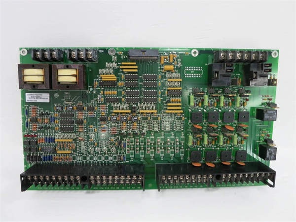
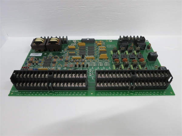
GE DS200DDTBG2A
The Real-World Problem It Solves
High-voltage LCI systems require isolated signal interfaces between field devices and control processors. The DS200DDTBG2A provides signal conditioning, scaling, and isolation, enabling safe and accurate connection of auxiliary I/O signals in harsh turbine environments.
Where you’ll typically find it:
- GE gas and steam turbine LCI starter systems
- Load Commutated Inverter drive controls
- Auxiliary pump and fan motor interfaces
- Current transformer (CT) and voltage monitoring applications
Bottom line: Isolated high-voltage I/O termination with signal conditioning for LCI systems.
Hardware Architecture & Under-the-Hood Logic
The DS200DDTBG2A interfaces with the DS200ADMA analog-to-digital module via a 60-pin high-density ribbon cable (TBPL). Power is supplied by the ADMA board. High-voltage AC inputs use step-down transformers, passive filtering, and buffers to deliver ±5 V peak-to-peak signals to the ADMA’s VCO inputs. High-current inputs use current sensing resistors with differential buffering. Four buffered analog outputs provide ±10 V output range with gain of two. Two 4-20 mA current outputs operate simultaneously with voltage outputs.
Signal flow:
- Field signals (HV AC, CT, digital inputs) connected to terminal blocks
- High-voltage AC signals stepped down via transformer
- Passive filtering applied to all analog inputs
- Current sensing resistors convert CT currents to voltage
- Differential buffers amplify and condition signals
- Conditioned signals routed to ADMA via 60-pin ribbon cable
- ADMA processes signals and sends output commands
- Analog outputs (voltage and 4-20 mA) generated
- Relay outputs asserted based on ADMA commands
- Status LEDs indicate channel and relay status
GE DS200DDTBG2A
Field Service Pitfalls: What Rookies Get Wrong
Incorrect jumper configuration causes signal type mismatch12 jumpers configure signal types and filtering. I’ve seen technicians leaving default jumper settings, causing digital inputs to read as analog or vice versa.
- Field Rule: Verify jumper configuration matches your application. Refer to GEI-100219 manual for jumper settings. Document each jumper’s position during commissioning. Test each channel with known signals—incorrect jumper settings will cause wrong readings. Re-verify jumpers after board replacement.
High-voltage input wiring without proper isolation creates safety hazardHV inputs rated for 693 V RMS. I’ve seen technicians using standard wire for HV inputs, risking arc flash and equipment damage.
- Field Rule: Use HV-rated wire and terminals for high-voltage AC inputs (rated >1000 V). Maintain minimum clearance distances per NEC. Use appropriate terminal blocks with proper creepage and clearance. Verify isolation with insulation tester before energizing. Never use low-voltage wire on HV inputs.
CT secondary open circuit causes dangerous voltage spikesOpen CT secondary creates lethal voltage. I’ve seen technicians disconnecting CT wiring while the system is energized, causing arcing and equipment damage.
- Field Rule: Never open-circuit a CT while primary current is flowing. Short the CT secondary terminals together before disconnecting. Use a shorting block or jumper wire. Install CTs with shorting switches for maintenance access. De-energize the system if shorting is not possible. Document CT shorting procedure.
Forgotten to verify analog output scaling causes monitoring errorsGain of two amplifies ±5 V to ±10 V. I’ve seen technicians expecting 0-5 V output while measuring ±10 V, causing SCADA alarms.
- Field Rule: Verify analog output scaling during commissioning. The board outputs ±10 V from ±5 V ADMA input (gain of two). Test with known input values—apply 0 V, verify 0 V output; apply +5 V, verify +10 V output. Document output scaling. Configure SCADA/PLC for ±10 V range, not 0-5 V.
Incorrect digital input voltage range causes false readingsInputs accept 24-250 VDC/AC. I’ve seen technicians applying 5 VDC signals, expecting the input to detect, resulting in no indication.
- Field Rule: Verify input voltage matches the digital input range (24-250 VDC/AC minimum). For 5 V or 12 V signals, use an interposing relay to convert to 24 V. Test input with a known 24 VDC source—input LED should illuminate. Document input voltage requirements. Never apply voltage below 24 V to digital inputs.
4-20 mA output miswiring causes loop failureCurrent outputs require proper loop wiring. I’ve seen technicians wiring the 4-20 mA output as a voltage source, causing zero current and lost monitoring.
- Field Rule: Verify 4-20 mA output is wired in series with the loop. The current output drives the loop—do not wire in parallel with voltage outputs. Test with a mA meter in series—should measure 4-20 mA proportional to input. Document loop wiring and load resistance (max 500-600 ohms typical). Never short the current output.
Ribbon cable misalignment causes pin damage60-pin ribbon cable not keyed. I’ve seen technicians offsetting the cable by one pin, blowing ADMA inputs.
- Field Rule: Verify ribbon cable orientation—Pin 1 typically marked with a red stripe. Align Pin 1 on the cable with Pin 1 on both the DDTB and ADMA boards. Use the manufacturer’s pinout diagram. Test I/O operation after installation. Document cable orientation and test results. Never force a ribbon cable—recheck orientation.
Ignoring jumper settings for G1 vs G2 version causes feature lossG2 lacks some G1 features. I’ve seen technicians expecting G1 features on G2 boards, discovering missing functionality during commissioning.
- Field Rule: Verify you have the correct board version for your application. G2 is a simplified version with fewer features than G1. Refer to GEI-100219 manual for feature comparison. If you need G1 features, order the correct board. Document board version and expected features. Never assume G1 and G2 are interchangeable.
Overlooking surge protection status causes board damage8 MOVs protect against transients. I’ve seen technicians ignoring MOVs after a surge event, leaving the board vulnerable to subsequent damage.
- Field Rule: Inspect MOVs after any surge event or lightning strike. Use a multimeter to test MOV resistance—should read high impedance (>1 MΩ). Replace any MOVs showing low resistance or physical damage. Document MOV inspection and replacement. Consider adding external surge protection for high-exposure installations.
Incorrect terminal block torque causes loose connectionsVibration loosens terminals over time. I’ve seen intermittent I/O faults traceable to undertorqued terminal screws.
- Field Rule: Torque terminal screws to 8-10 in-lbs maximum. Use a calibrated torque wrench. Re-torque after initial heat cycle (24 hours). Schedule periodic re-torque (monthly or per plant maintenance). For stranded wire, use wire ferrules to prevent strand breakout. Document torque values and re-torque schedule.
Commercial Availability & Pricing Note
Please note: The listed price is for reference only and is not binding. Final pricing and terms are subject to negotiation based on current market conditions and availability.


