
Description
Hard-Numbers: Technical Specifications
-
Input Voltage: 115 VAC or 230 VAC (selectable/jumper configurable), 50/60 Hz
-
Output Voltages: +24 VDC (5A), -24 VDC (5A), +5 VDC (2A)
-
Total Power: Approximately 250W combined output capacity
-
Efficiency: ≥92%
-
Input Power Transformer: 38-115 VAC control power tap
-
Fuse Protection: Independent fuses for 115VAC input, +24VDC, and -24VDC outputs with visual indicators
-
Configuration: Seven 4-position DIP switches, twelve configurable jumpers for voltage scaling and current limits
-
Operating Temperature: -40°C to +70°C (-40°F to 158°F)
-
Storage Temperature: -40°C to +85°C
-
Humidity: 5% to 95% non-condensing
-
Vibration: 0.05 g RMS random, 5 Hz to 500 Hz
-
Shock: 15 g, 20 ms half-sine
-
Dimensions: 220 mm × 220 mm × 80 mm (approximate)
-
Weight: 1.5 kg (3.3 lbs)
-
Mounting: Panel or chassis mount with screw terminals
-
IP Rating: IP40 (front), IP20 (rear)

GE DS200DCFBG1BJB
The Real-World Problem It Solves
You know the scenario: a Mark V turbine control rack goes dark because the original power supply can’t handle the inrush current of modern IGBT drives, or a blown fuse takes down the entire +24V field bus without warning. The DS200DCFBG1BJB eliminates these headaches with robust transformer-isolated outputs, individual fuse monitoring for each rail, and DIP-switch configurable voltage scaling that lets you fine-tune output levels for different drive applications. It’s not just a power supply—it’s a power distribution and protection system that keeps your Mark V alive through voltage sags and transient faults.
Where you’ll typically find it:
-
EX2000 excitation system cabinets providing field power to generator exciters
-
AC2000/DC2000 IGBT drive chassis for gas turbine fuel valve servos
-
Mark V Speedtronic control racks in Frame 7/9 gas turbine applications
Bottom line: It converts raw 115VAC panel power into clean, isolated DC rails with visual fuse status indication—preventing ground loops and giving you early warning before a power fault trips your turbine.
Hardware Architecture & Under-the-Hood Logic
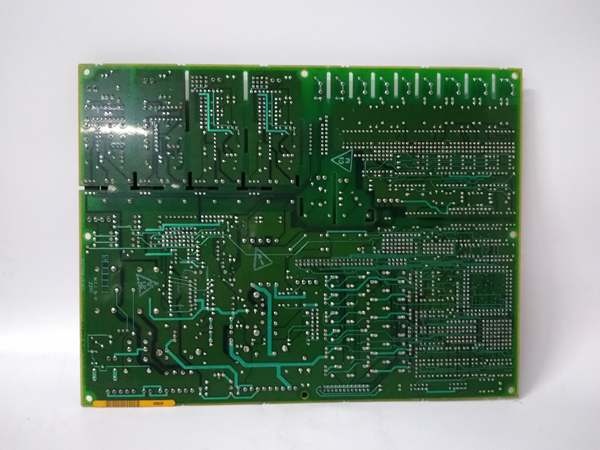
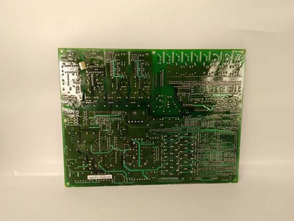
The DS200DCFBG1BJB is a linear/transformer-based power supply, not a switch-mode design. This is intentional—Mark V systems prioritize noise immunity and reliability over efficiency. The board occupies a large footprint (220mm square) to accommodate the power transformer, filter capacitors, and heat sinks required for linear regulation. It mounts in the drive chassis and distributes power via screw terminals to downstream boards.
Signal flow and power distribution logic:
-
AC Input: 115/230 VAC enters through fused input, passes through EMI filtering to prevent noise injection onto the control power bus
-
Transformer Isolation: Multi-tap power transformer provides galvanic isolation and voltage step-down for the three output rails—this is critical for preventing ground loops in sensitive analog control circuits
-
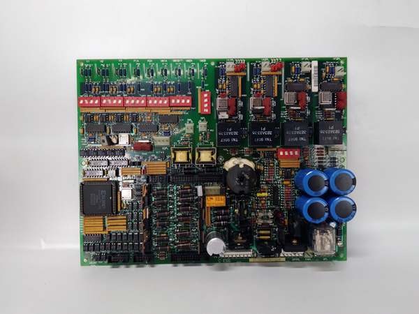
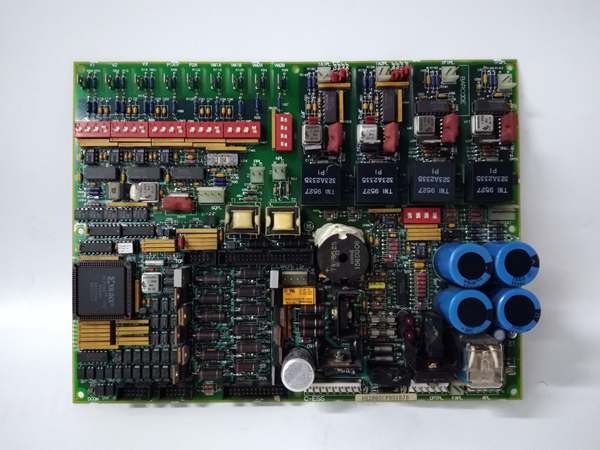
Rectification & Filtering: Full-wave bridges and large electrolytic capacitors convert AC to raw DC; linear regulators (not switching) provide clean, low-noise output
-
Voltage Scaling: DIP switches (particularly SW4) adjust regulator reference voltages to compensate for line drop or specific drive requirements—no pot tweaking required
-
Fuse Monitoring: Neon lamp indicates 115VAC input fuse status; LEDs monitor +24V and -24V output fuses—visual indication only, no remote alarm contacts
-
Distribution: Screw terminals on the board edge distribute power to SDCC/LDCC drive control boards, I/O modules, and chassis cooling fans
GE DS200DCFBG1BJB
Field Service Pitfalls: What Rookies Get Wrong
Assuming It’s a Simple “Black Box” Power Supply Rookies treat this like an off-the-shelf DIN rail supply—swap it, power up, and walk away. It’s not. The DS200DCFBG1BJB has twelve jumpers and seven DIP switches that must match the original configuration for your specific drive application (EX2000 vs. AC2000 vs. FC2000). Wrong settings cause overvoltage trips or insufficient current capacity.
Field Rule: Photograph the DIP switch and jumper positions on the old board before removal. Transfer settings exactly to the replacement. Check GE manual GEH-6375 for the configuration table matching your drive model—don’t guess.
Ignoring the 115VAC Neon Indicator The neon lamp on the board face indicates input fuse status, but it only works when the fuse is good. Rookies see “no light” and assume the fuse is blown, but a failed neon lamp or loose connection gives the same indication. They replace fuses that aren’t blown or miss blown fuses because the lamp failed.
Quick Fix: Verify with a multimeter across the fuse holder terminals—line voltage present means fuse is good regardless of neon status. If the neon lamp is out but voltage is present, mark the board for lamp replacement during next outage. Don’t rely solely on visual indicators for critical power status.
Forgetting the -24V Rail Most field devices use +24V, so rookies focus there and ignore the -24V output. But Mark V analog I/O and some drive circuits require the negative rail for bipolar signal conditioning. A blown -24V fuse causes erratic analog readings or servo drift that looks like a control problem, not a power problem.
Field Rule: Always check all three output voltages (+24V, -24V, +5V) with a meter during commissioning. The LEDs only indicate fuse status, not voltage accuracy. A fuse can be good but output low due to regulator failure—verify with load connected, not just open-circuit voltage.


