
Description
Hard-Numbers: Technical Specifications
- Feedback Inputs: 4 tachometer inputs (AC/DC tach), 5 current transformer (CT) inputs (enhanced vs base revision)
- Tachometer Input Range: 0-100 VAC (typical), 0-200 VDC (DC tach optional)
- CT Input Range: 0-5 A secondary, compatible with standard 5A CTs
- Output Signals: Digital feedback to drive controller via backplane, 2x 4-20 mA analog outputs (independent)
- Isolation: Channel-to-channel 1500V RMS, backplane isolation 500V RMS
- Sampling Rate: 5 kHz per channel (enhanced vs 2 kHz on base)
- Accuracy: ±0.05% of reading (speed enhanced), ±0.3% of reading (current enhanced)
- Backplane Interface: VME-style 96-pin DIN connector
- Power Requirements: +5 VDC @ 3.5 A, +15 VDC @ 1.2 A (higher due to enhanced features)
- Operating Temperature: 0°C to 55°C (32°F to 131°F)
- LED Indicators: Power, Tachometer Status (4), CT Status (5), Fault, Analog Output Status (2)
- Diagnostic Capabilities: Enhanced on-board diagnostics, cross-channel monitoring, signal loss detection
- Terminal Block: Removable screw terminal for field wiring

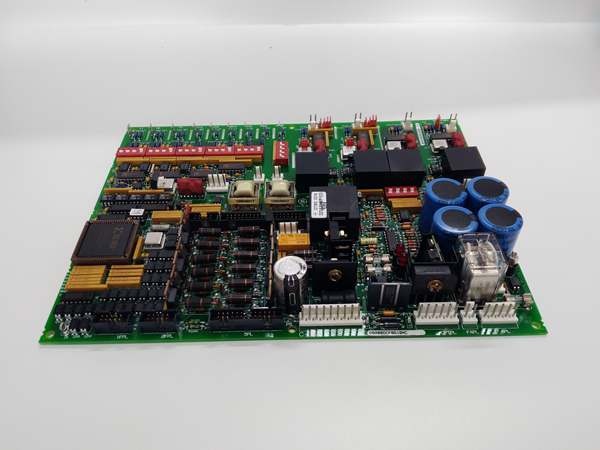
GE DS200DCFBG1B
The Real-World Problem It Solves
Multi-motor drive systems require coordinated feedback from multiple sources. The DS200DCFBG1B provides enhanced feedback capacity with higher resolution and independent analog outputs.
Where you’ll typically find it:
- GE DC multi-motor drive systems
- Coordinated line shaft drives
- Turbine auxiliary drive controls
- Complex motor synchronization applications
Bottom line: Enhanced multi-channel feedback for complex drive systems.
Hardware Architecture & Under-the-Hood Logic
The DS200DCFBG1B builds on base design with enhanced capabilities. Four tachometer inputs and five CT inputs provide multi-motor feedback. Enhanced sampling rate (5 kHz) improves feedback resolution for precision applications. Dual independent 4-20 mA outputs provide external monitoring or cascaded control.
Signal flow:
- Up to 4 tachometer inputs received (AC or DC tach)
- Tach signals conditioned and filtered
- ADC converts tach signals to digital speed values (5 kHz sampling)
- Up to 5 CT secondary currents converted to voltage via shunts
- CT voltages digitized via ADC (5 kHz sampling)
- Microcontroller processes all feedback data
- Digital feedback transmitted to drive controller via backplane
- Dual 4-20 mA outputs generated for external monitoring
- Cross-channel monitoring and fault detection active
- LEDs indicate all channel status and fault conditions
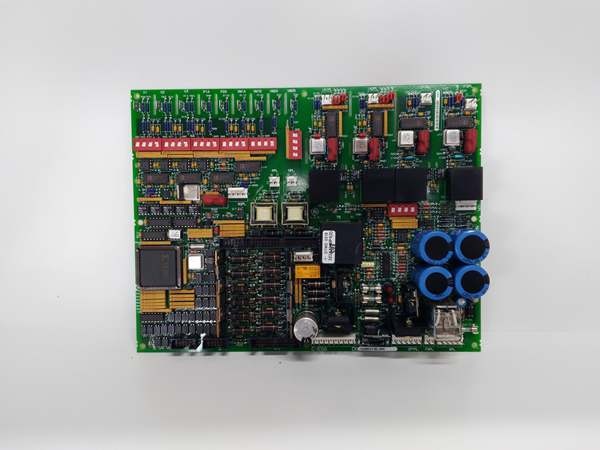
GE DS200DCFBG1B
Field Service Pitfalls: What Rookies Get Wrong
Channel cross-assignment causes motor mismatchFour tach inputs require precise mapping. I’ve seen technicians connecting Motor 2 tach to Channel 1 input, causing the controller to drive Motor 1 based on Motor 2 speed.
- Field Rule: Verify channel-to-motor assignment before wiring. Document which channel corresponds to each motor (e.g., Channel 1 = Main Drive Motor, Channel 2 = Feed Motor). Test each channel by rotating the associated motor and verifying feedback on the correct channel. Document channel assignments and test results. Re-verify after any motor or cabling changes.
Enhanced CT inputs require larger gauge wiringFive CT inputs at 5A total current. I’ve seen technicians using 18 AWG wire on multiple CT secondaries, causing voltage drop and measurement errors.
- Field Rule: Use appropriate wire gauge for CT secondary current. For multiple CTs on the same board, calculate total current and size wire accordingly—typically 14-16 AWG for 2-3 CTs sharing a neutral return. Measure voltage drop at full load—keep below 1%. Document wire gauge per CT input. Never undersize CT wiring—measurement accuracy depends on low-impedance secondary circuits.
Independent analog outputs require separate configurationDual 4-20 mA outputs operate independently. I’ve seen technicians configuring both outputs for the same channel, wasting the enhanced capability.
- Field Rule: Configure analog outputs for independent monitoring or control functions. For example, Output 1 = Motor 1 speed (0-2000 RPM = 4-20 mA), Output 2 = Total current (0-500A = 4-20 mA). Test each output independently with a mA meter. Document output configurations and test results. The B revision’s dual outputs enable advanced control—utilize both.
Cross-channel monitoring threshold too sensitiveMulti-channel monitoring detects discrepancies. I’ve seen technicians setting 2% discrepancy threshold, causing nuisance trips on normal speed variations between motors.
- Field Rule: Set cross-channel discrepancy threshold based on application requirements. For coordinated motors running at the same speed, 5-10% threshold is typical. For master-slave configurations, thresholds can be higher. Test by intentionally creating a speed mismatch—trip should occur only at the configured threshold. Document threshold settings and test results.
Hot-swapping channel wiring causes transients on all channelsEnhanced board is more sensitive to transients. I’ve seen technicians disconnecting one CT while the drive is running, causing all CT channels to show erratic readings.
- Field Rule: Follow strict lockout/tagout procedures before modifying any feedback wiring. De-energize the entire drive system before working on any CT or tach inputs. For CTs, short the secondary of the specific CT being worked on—even with the drive off, induced voltages can occur. Document LOTO procedures. Never work on live feedback wiring on the B revision.
Forgotten to enable enhanced sampling rate causes underutilization5 kHz sampling disabled by default. I’ve seen technicians installing the B revision board and configuring it at 2 kHz (base revision settings), wasting the enhanced capability.
- Field Rule: Enable enhanced sampling rate (5 kHz) during commissioning. Configure all channels for high-speed operation if your application requires precision. Verify sampling rate configuration via software tool. Document enabled features and sampling rate. The B revision costs more—utilize the enhanced resolution to justify the investment.
Incorrect analog output scaling causes monitoring errorsDual outputs require independent scaling. I’ve seen technicians applying the same scaling to both outputs, causing Output 2 to read incorrectly for its assigned parameter.
- Field Rule: Configure each analog output with independent scaling. Use software tools to set minimum/maximum values for each output. Test with known input values—apply 50% of range, verify 12 mA on the correct output. Document scaling for each output. Re-verify after any board replacement or configuration change.
Overlooking multiple tach status LEDs causes delayed diagnosisFour tach LEDs provide granular status. I’ve seen technicians ignoring a single flashing “Tach 3 Fault” LED, missing a developing motor fault for weeks.
- Field Rule: Monitor all four tach status LEDs during routine inspections. Each LED corresponds to a specific channel—any deviation from normal patterns indicates a problem on that channel. Investigate immediately—cross-channel monitoring may mask individual channel issues. Document normal LED patterns for all channels. Set up automated alerts if your SCADA system supports reading individual channel health.
CT shorting bar miswired causes current分流Five CT inputs require careful shorting. I’ve seen technicians installing a single shorting bar across all five CT terminals, creating parallel paths and measurement errors.
- Field Rule: Each CT secondary should have its own shorting mechanism. Use individual shorting blocks or jumpers. Never share shorting bars between CTs—this creates parallel current paths and measurement inaccuracy. Document CT shorting configuration. When working on one CT, short only that specific CT’s secondary.
Insufficient power supply causes erratic operationHigher current draw (3.5A @ 5V) strains supply. I’ve seen technicians replacing the B revision board without verifying power supply capacity, causing voltage sag and unstable feedback.
- Field Rule: Verify the 5V power supply capacity before installing the B revision board. The B revision draws 3.5A—ensure supply can handle this load plus other boards. Measure 5V at the board connector under full load—should be 4.75-5.25V. If voltage sags below 4.75V, upgrade the power supply. Document power supply capacity and voltage measurements.
Commercial Availability & Pricing Note
Please note: The listed price is for reference only and is not binding. Final pricing and terms are subject to negotiation based on current market conditions and availability.


