

Description
Hard-Numbers: Technical Specifications
- Processor Type: Intel 80386DX or compatible, 33 MHz clock speed
- Memory: 2 MB RAM (expandable to 4 MB), 512 KB EPROM (firmware)
- Backplane Interface: VME-style 96-pin DIN connector
- Communication Ports: Dual RS-232C (DB-9), optional RS-485 Modbus RTU
- I/O Expansion: 16 digital I/O channels (8 in, 8 out) via ribbon cable
- Power Requirements: +5 VDC @ 4.0 A, +12 VDC @ 0.5 A
- Operating Temperature: 0°C to 55°C (32°F to 131°F)
- Watchdog Timer: Programmable 1-255 seconds
- Diagnostic Port: Rear diagnostic connector for maintenance interface
- LED Indicators: Power, Run, Fault, Communication (2), I/O Status (16)
- Execution Cycle Time: 10-20 ms typical for complex logic
- Software Compatibility: GE Speedtronic Mark V Toolbox, C-language applications
- Battery Backup: 3.6V Lithium for RAM retention (3-5 years typical)

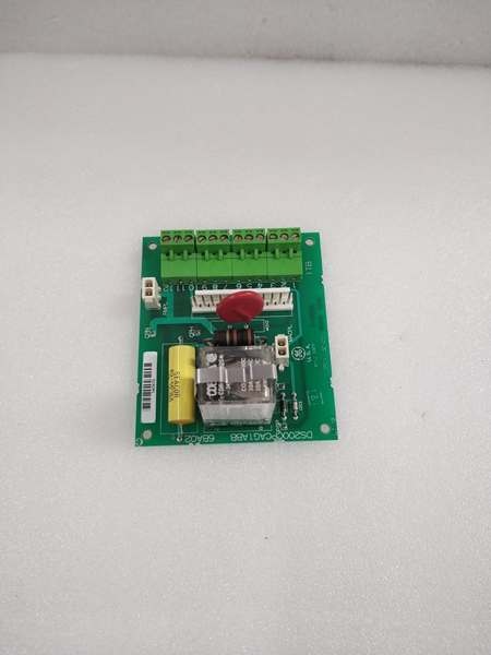
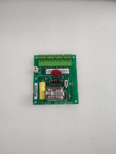
GE DS200CPCAG1ABB
The Real-World Problem It Solves
Main controller CPUs lack processing power for complex algorithms. The DS200CPCAG1ABB provides co-processing capability, enabling advanced control functions without slowing the main controller.
Where you’ll typically find it:
- GE gas and steam turbine control systems (Mark V)
- Advanced control logic implementation
- Sequencer and state machine control
- Custom algorithm applications
Bottom line: Enhanced processing capability for advanced turbine control functions.
Hardware Architecture & Under-the-Hood Logic
The DS200CPCAG1ABB uses an Intel 80386DX microprocessor as the co-processor. This board interfaces with the main turbine control CPU via the VME backplane, sharing data and offloading processing tasks. Dual RS-232 ports provide external communication for programming and diagnostics. Expanded RAM allows complex algorithm storage and execution. A watchdog timer monitors co-processor health.
Signal flow:
- Main controller CPU exchanges data with co-processor via VME backplane
- Co-processor fetches instructions from EPROM and data from RAM
- Logic and algorithms executed on 80386DX processor
- Results written back to main controller via backplane
- RS-232 ports provide external communication for programming
- I/O channels interface with external devices via ribbon cable
- Watchdog timer monitors processor health—trips on fault
- Battery backup maintains RAM data during power loss
- LEDs indicate processor, communication, and I/O status
GE DS200CPCAG1ABB
Field Service Pitfalls: What Rookies Get Wrong
Forgotten to update application firmware causes compatibility mismatchCo-processor firmware must match main controller. I’ve seen technicians upgrading the main CPU firmware without updating the co-processor, causing communication failures and control errors.
- Field Rule: Always update co-processor firmware in tandem with main controller firmware. Verify firmware version compatibility matrix before any upgrade. Document firmware versions before and after upgrade. Test control functionality after firmware update before placing the turbine online. Maintain a backup of the working firmware image.
Watchdog timer misconfiguration causes nuisance tripsTimeout too short trips on normal processing delays. I’ve seen technicians setting watchdog to 5 seconds on applications requiring 10-15 seconds for complex calculations, causing unnecessary turbine trips.
- Field Rule: Set watchdog timeout to 2-3x maximum expected execution time. For typical applications, 20-30 seconds is sufficient. Test watchdog operation by simulating a processor stall (hold CPU in debug mode). Never set watchdog below minimum execution time. Document watchdog setting and test results. For complex algorithms, consider temporarily disabling watchdog during development.
Battery replacement causes RAM data lossBattery lasts 3-5 years. I’ve seen technicians replacing the battery without backing up RAM data, losing custom algorithms and calibration data.
- Field Rule: Back up RAM data to EPROM or external storage before replacing the battery. Document the backup procedure and date. Replace battery with exact same type (3.6V Lithium). After replacement, verify RAM data integrity and restore from backup if corrupted. Schedule battery replacement proactively (every 3 years for critical applications). Document battery replacement date.
RS-232 port misconfiguration causes communication failuresBaud rate and parity must match host device. I’ve seen technicians attempting communication with mismatched settings (9600 vs 19200 baud), resulting in garbage data or no response.
- Field Rule: Verify RS-232 port configuration matches the programming device. Common settings: 19200 baud, 8 data bits, no parity, 1 终止 bit. Document port configuration for each application. Test communication with a known-good cable and terminal program. For Modbus communication, verify slave address and register map. Re-verify configuration after any cable or device change.
Hot-swapping while processor is active corrupts RAMRemoving the board while powered causes data corruption. I’ve seen technicians pulling the co-processor board live to troubleshoot, corrupting RAM algorithms.
- Field Rule: Follow proper shutdown procedures before removing the co-processor board. Place the turbine in a safe state (shutdown or manual mode). Allow the processor to complete current execution cycle before power removal. Never hot-swap co-processor boards—use proper lockout/tagout procedures. Document shutdown procedures and train all technicians. RAM corruption requires complete algorithm reload.
Forgotten to verify I/O ribbon cable orientation causes damageRibbon cables are not keyed. I’ve seen technicians installing I/O ribbon cables backwards, blowing the I/O driver chips.
- Field Rule: Verify ribbon cable orientation—Pin 1 typically marked with a red stripe or arrow. Pin 1 on the cable must align with Pin 1 on both connectors. Use the manufacturer’s pinout diagram. Test I/O operation after installation with known inputs and outputs. Document cable orientation and test results. Never force a ribbon cable—recheck orientation if it doesn’t seat easily.
Insufficient RAM causes algorithm execution failures2 MB RAM limits complex algorithms. I’ve seen technicians developing complex control logic that exceeds available RAM, causing execution failures or watchdog trips.
- Field Rule: Verify RAM requirements before algorithm development. Use memory usage analysis tools to estimate RAM consumption. For algorithms requiring >2 MB, upgrade to 4 MB RAM expansion board. Test algorithm execution with worst-case data sets during development. Document RAM usage and upgrade history. Monitor RAM usage during operation—approaching 90% indicates need for upgrade.
Overlooking processor load causes degraded performance80386DX at 33 MHz has limits. I’ve seen technicians loading the co-processor with multiple complex algorithms, causing execution times to exceed watchdog timeout.
- Field Rule: Monitor processor load during operation. Use diagnostic tools to measure CPU utilization and execution time. For applications exceeding 80% CPU load, consider offloading some functions to a second co-processor board or upgrading the main controller. Document CPU utilization trends. Sudden increases in load indicate algorithm inefficiency or memory leaks.
Incorrect interrupt priority causes missed eventsInterrupts prioritize time-critical tasks. I’ve seen technicians assigning low priority to safety-critical interrupts, causing delayed responses and potential trips.
- Field Rule: Assign interrupt priorities based on criticality. Safety-critical inputs (overspeed, emergency shutdown) get highest priority. Non-critical tasks (data logging, communication) get lower priority. Test interrupt response time with simulated events. Document interrupt priorities and test results. For time-critical applications, verify response time meets safety requirements.
Ignoring “Fault” LED causes delayed diagnosisFault LED indicates processor or hardware failure. I’ve seen technicians ignoring a flashing Fault LED, allowing the co-processor to run in degraded mode until complete failure.
- Field Rule: Monitor Fault LED during routine inspections. Any flashing or solid-on Fault LED indicates a problem—investigate immediately. Use diagnostic software to read fault codes. Common faults: watchdog timeout, memory parity error, bus error. Document fault codes and corrective actions. Replace boards with recurring unexplained faults.
Commercial Availability & Pricing Note
Please note: The listed price is for reference only and is not binding. Final pricing and terms are subject to negotiation based on current market conditions and availability.


