
Description
Hard-Numbers: Technical Specifications
- Fault Capture Channels: 80 digital fault inputs, 24 analog trigger inputs
- Capture Depth: Up to 2048 pre-trigger events, 1024 post-trigger events
- Sampling Rate: 2 kHz digital, 200 Hz analog (enhanced vs base revision)
- Time Stamping: 0.5 ms resolution (internal clock)
- Backplane Interface: VME-style 96-pin DIN connector
- Non-Volatile Memory: 256 KB EEPROM for fault log storage (extended)
- Trigger Modes: Edge-triggered, level-triggered, software-triggered, pattern-triggered
- Analog Input Range: 0-10 VDC, 4-20 mA, ±10 VDC (differential), ±5 VDC
- Digital Input Voltage: 24 VDC ±20%, dry contact (5-30 VDC wetting)
- Power Requirements: +5 VDC @ 3.0 A, +15 VDC @ 0.7 A
- Operating Temperature: 0°C to 55°C (32°F to 131°F)
- LED Indicators: Power, Fault Capture Active, Memory Full, Communication Status, Channel Health (multiple)
- Diagnostic Capabilities: On-board diagnostics, fault history logging, trend capture, pattern recognition
- Terminal Block: Removable screw terminal for trigger inputs

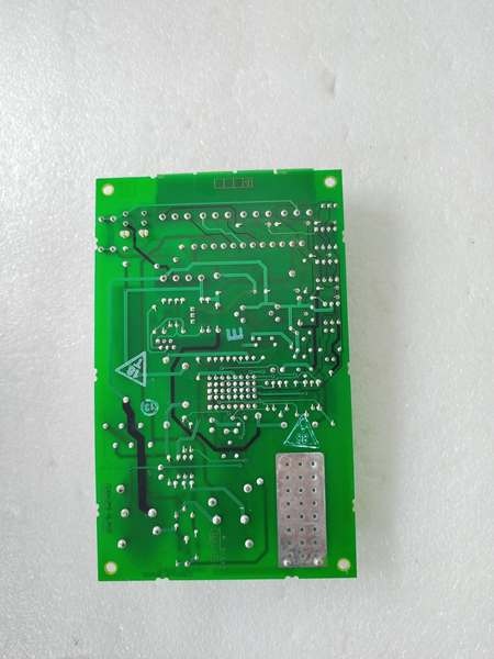
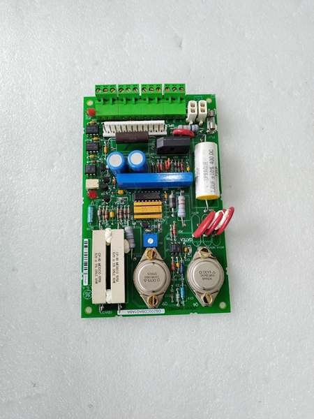
GE DS200CDBAG1A
The Real-World Problem It Solves
Turbine trips require high-speed data capture to determine root cause. The DS200CDBAG1ABA provides enhanced capture capabilities with extended memory and higher sampling rates, enabling precise fault analysis.
Where you’ll typically find it:
- GE gas and steam turbine control systems (Mark V)
- Generator protection and monitoring systems
- Critical drive and auxiliary systems
- Retrofit diagnostic applications for legacy controls
Bottom line: Enhanced fault capture for precise turbine trip diagnosis.
Hardware Architecture & Under-the-Hood Logic
The DS200CDBAG1ABA builds on the base design with enhanced capabilities. High-speed digital capture circuitry records system state at 2 kHz. Analog trigger inputs and digital fault inputs are continuously monitored. Pattern-triggered capture enables complex fault detection based on multiple input conditions. Enhanced non-volatile memory stores extended fault history.
Signal flow:
- System continuously monitors 80 digital fault inputs and 24 analog triggers
- Analog inputs sampled at 200 Hz for trend and trigger detection
- Digital inputs sampled at 2 kHz for high-speed capture
- Pattern recognition logic monitors input combinations for complex triggers
- Trigger condition met (edge, level, or pattern)
- Board captures up to 2048 pre-trigger events from circular buffer
- Post-trigger events captured and stored (up to 1024 events)
- Fault data with 0.5 ms timestamps stored in extended EEPROM
- Data available for retrieval via VME backplane or serial port
GE DS200CDBAG1A
Field Service Pitfalls: What Rookies Get Wrong
Pattern trigger configuration errors cause missed faultsComplex AND/OR logic requires precise setup. I’ve seen technicians configuring “AND” triggers that require all inputs to fault simultaneously, missing the actual trip that only triggered one input.
- Field Rule: Use “OR” logic for fault capture where any input fault should trigger capture. Use “AND” logic only for multi-input fault conditions (e.g., overspeed AND low lube oil pressure). Test each pattern trigger scenario during commissioning—simulate faults on each input independently. Document trigger logic and test results. Review and update trigger patterns after any system modification.
Trigger level set too sensitive causes nuisance capturesEnhanced sensitivity captures normal transients. I’ve seen technicians setting triggers at 3% of nominal on the ABA revision, filling extended memory with nuisance data within hours.
- Field Rule: Set trigger threshold at 10-15% above nominal operating level for analog triggers, or 2-3x normal operating range. Test trigger sensitivity with normal operation—should not capture during normal transients. The ABA revision’s enhanced sensitivity requires higher thresholds than the base board. Document trigger levels and test results. Review captured data weekly—if full of nuisance events, adjust thresholds upward.
Forgotten to clear fault log before testing causes confusionExtended memory holds more old data. I’ve seen technicians failing to clear the 256 KB log before commissioning, analyzing data from weeks or months ago as current faults.
- Field Rule: Clear the fault log before any planned test or commissioning activity. Document the “before” fault log status for baseline comparison. After capturing test data, clear the log again to prevent confusion. Extended memory means more old data—be extra vigilant about clearing. Document fault log clearing procedures and timestamps.
Analog input wiring errors cause false triggers24 analog channels increase complexity. I’ve seen technicians grounding the shield at both ends on differential inputs, causing oscillating triggers and filling memory.
- Field Rule: For differential analog inputs, ground the shield at the cabinet end only. Maintain proper polarity (+ to +, – to -). Measure ground potential between board and field device—should be less than 1 VAC. With 24 channels, verify each channel’s wiring independently. Document wiring configuration and test results. Use filtering to reduce noise sensitivity on all channels.
Enhanced memory overflow causes data loss2048 pre-trigger events fill quickly on high-frequency faults. I’ve seen technicians assuming extended memory prevents overflow, but high-speed faults still fill the buffer.
- Field Rule: Configure pre-trigger capture depth appropriate to your application (512-1024 events typical even with extended memory). Monitor memory status LED—if flashing “Memory Full,” download data and clear log promptly. The ABA revision’s higher sampling rate fills memory faster than the base board. Document memory configuration and download schedule.
Hot-swapping while capturing corrupts extended dataRemoving the board disrupts data integrity. I’ve seen technicians pulling boards to download data while capture is active, causing corrupted 256 KB fault logs.
- Field Rule: Stop active fault capture before removing the board. Download fault data via VME backplane or serial port without removing the board. If board removal is necessary, ensure capture is disabled and memory is empty. Extended memory takes longer to download—account for this in maintenance schedules. Never hot-swap diagnostic boards.
Incorrect timestamp configuration causes root cause confusion0.5 ms resolution requires precise sync. I’ve seen technicians ignoring timestamp synchronization on the ABA revision, leading to incorrect root cause conclusions when correlating events across multiple boards.
- Field Rule: Synchronize the diagnostic board clock with the master clock or GPS time source during commissioning. The enhanced 0.5 ms resolution requires tighter sync tolerance than the base board. Verify timestamp accuracy weekly—should be within ±5 ms of master clock. Document clock sync procedure and schedule. For multi-board applications, synchronize all boards to the same time source.
Forgotten to enable enhanced features causes underutilizationPattern triggers and enhanced features disabled by default. I’ve seen technicians installing ABA revision boards and configuring them exactly like base revision boards, wasting the enhanced capabilities.
- Field Rule: Enable pattern-triggered capture, enhanced sampling rates (2 kHz digital, 200 Hz analog), and extended memory usage during commissioning. Configure all 24 analog inputs if your application requires it. Document all enabled features and configurations. The ABA revision costs more—utilize all enhanced features to justify the investment.
Overlooking analog capture resolution causes missed transients200 Hz sampling still misses fast events if misconfigured. I’ve seen technicians using 200 Hz sampling but enabling 50 Hz filtering, defeating the enhanced resolution.
- Field Rule: Configure analog sampling rate and filter bandwidth appropriately. The ABA revision supports up to 200 Hz—use this for high-frequency transients. Set filter bandwidth higher than the highest frequency of interest (e.g., 100 Hz filter for 60 Hz systems). Verify sampling rate and filter configuration via software tool. Document all settings and test with a step input.
Ignoring multiple channel health LEDs causes delayed troubleshootingMultiple health LEDs provide granular status. I’ve seen technicians ignoring a single flashing “Channel 12 Fault” LED among the 24 channel indicators, missing a developing fault for weeks.
- Field Rule: Monitor all channel health LEDs during routine inspections. The ABA revision has multiple individual channel status indicators—check each one. Any deviation from normal patterns indicates a problem—investigate immediately. Document normal LED patterns for all channels. Set up automated alerts if your SCADA system supports reading channel health.
Commercial Availability & Pricing Note
Please note: The listed price is for reference only and is not binding. Final pricing and terms are subject to negotiation based on current market conditions and availability.


