
Description
Hard-Numbers: Technical Specifications
- Input Channels: 8 digital inputs (dry contact or 24 VDC), 4 analog inputs (0-10 VDC or 4-20 mA)
- Output Channels: 4 digital outputs (relay or open-collector, 24 VDC), 2 analog outputs (0-10 VDC or 4-20 mA)
- Communication Interface: RS-485 Modbus RTU, optional Profibus DP
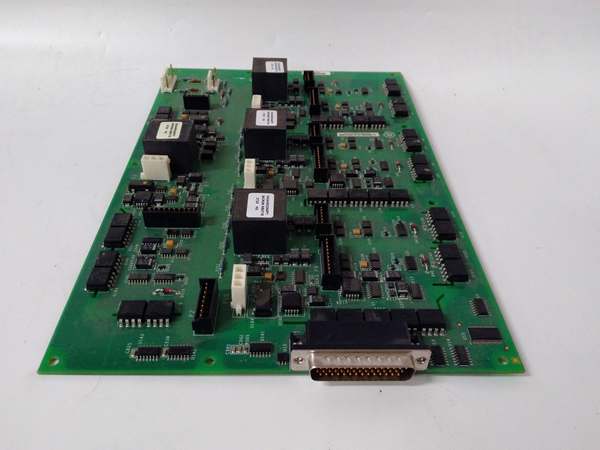
- Backplane Interface: VME-style 96-pin DIN connector
- Digital Input Voltage: 24 VDC ±20%, dry contact (5-30 VDC wetting)
- Analog Input Resolution: 12-bit ADC
- Analog Output Resolution: 12-bit DAC
- Relay Contact Rating: 5 A @ 250 VAC resistive
- Power Requirements: +5 VDC @ 3.0 A, +15 VDC @ 0.8 A, -15 VDC @ 0.3 A
- Operating Temperature: 0°C to 55°C (32°F to 131°F)
- LED Indicators: Power, Input Status (8), Output Status (4), Communication Active, Fault
- Diagnostic Capabilities: On-board diagnostics via software tools
- Terminal Block: Removable screw terminal for field wiring
- Isolation: Channel-to-channel and channel-to-backplane isolation, 1500V RMS

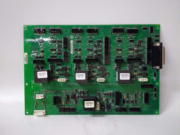
GE IS210AEDBH4AGD
The Real-World Problem It Solves
Drive status must be integrated into turbine control for coordinated operation. The DS200ADMAH1A provides drive monitoring and communication, enabling seamless integration between motor drives and control systems.
Where you’ll typically find it:
- GE gas and steam turbine auxiliary drive systems
- Motor-driven pump and fan control
- Turbine lube oil and hydraulic pump monitoring
- Generator excitation and auxiliary systems
Bottom line: Drive-to-control interface with status monitoring and communication.
Hardware Architecture & Under-the-Hood Logic
The DS200ADMAH1A uses isolated digital and analog input/output circuits to interface with drive controllers. A microcontroller manages I/O processing, communication protocols (Modbus/Profibus), and diagnostic functions. The board interfaces with the turbine control CPU via the VME backplane, exchanging drive status and control commands.
Signal flow:
- Digital inputs (drive status, fault signals) received from drive controllers
- Analog inputs (current, speed feedback) received and digitized
- Microcontroller processes input data and applies filtering
- Status data transmitted to turbine control CPU via VME backplane
- Control commands received from CPU via backplane
- Digital outputs (drive enable, start/终止 commands) asserted
- Analog outputs (speed reference, torque limit) generated
- Communication port exchanges data with external systems (Modbus/Profibus)
- Diagnostics monitor I/O health and fault conditions
GE IS210AEDBH4AGD
Field Service Pitfalls: What Rookies Get Wrong
Digital input wiring to wrong voltage level destroys inputsInputs rated for 24 VDC fail at 120 VAC. I’ve seen technicians wiring 120 VAC control signals to 24 VDC inputs, blowing the input circuitry.
- Field Rule: Verify input voltage rating before wiring (24 VDC ±20% max). Use a multimeter to test field signals before connecting. For 120 VAC signals, use an interposing relay with 24 VDC contacts. Document input voltage and wiring configuration. Never apply voltage above rated value—input protection will not survive sustained overvoltage.
Forgotten to configure Modbus slave address causes communication failuresBoard defaults to address 1. I’ve seen technicians leaving default settings on multiple boards, causing Modbus address conflicts and communication lockup.
- Field Rule: Verify Modbus slave address is unique before network integration. Document the address assignment for all devices on the Modbus network. Test communication with a Modbus master before bringing the system online. Re-verify address after any board replacement. Never duplicate addresses on the same Modbus network.
Analog input scaling mismatch causes incorrect feedbackBoard default scaling is 0-10 VDC = 0-100% output. I’ve seen technicians connecting 4-20 mA without changing scaling, resulting in 20 mA reading as 50% instead of 100%.
- Field Rule: Configure analog input scaling via software tool or DIP switches. For 4-20 mA inputs, set scaling to 4-20 mA = 0-100% output. Test with a calibrated signal source (4 mA = 0%, 12 mA = 50%, 20 mA = 100%). Document scaling values and test results. Re-verify scaling after board replacement or firmware upgrade.
Improper grounding causes intermittent communication noiseGround loops corrupt Modbus signals. I’ve seen communication failures traceable to floating racks or missing ground bonds between cabinets.
- Field Rule: Ground all cabinets to the same earth ground. Verify ground continuity between cabinets—should be less than 1 ohm. Never ground the RS-485 shield at multiple points—ground at the master device only. Use twisted shielded pair for Modbus with proper termination (120 ohm at both ends). Document grounding configuration and test results.
Relay contact overload causes weldingRelays rated 5 A fail at 10 A. I’ve seen technicians wiring motor contactor coils directly to board relay outputs, causing contact welding and failure.
- Field Rule: Verify load current before connecting. For inductive loads (contactors, solenoids), use an interposing relay or contactor rated for the load. Board relays are rated for 5 A resistive, 3 A inductive. Never exceed the contact rating. Document load type and current. Use snubber circuits across inductive loads.
Hot-swapping without proper procedure damages the boardRemoving the board while powered can damage components. I’ve seen technicians pulling boards live to test communication, causing blown components or backplane damage.
- Field Rule: Follow proper shutdown procedures before removing any Mark V board. Place the drive or turbine in a safe state (终止, de-energize). De-energize the control cabinet or rack before board removal. Never hot-swap monitor boards—use proper lockout/tagout procedures. Document shutdown procedures and train all technicians.
Ignoring LED indicators delays fault diagnosisLEDs provide real-time status. I’ve seen technicians ignoring flashing fault LEDs, missing drive protection faults until catastrophic failure.
- Field Rule: Monitor LED indicators during normal operation—Power (solid green), Input Status (illuminated when inputs active), Output Status (illuminated when outputs active), Fault (flashing indicates fault). Document normal LED patterns. Any deviation from normal patterns indicates a problem—investigate immediately.
Forgotten to verify analog output scaling causes incorrect speed referenceBoard default scaling is 0-10 VDC = 0-100% speed. I’ve seen technicians configuring drives for 4-20 mA speed reference while board outputs 0-10 VDC, causing speed mismatches.
- Field Rule: Verify analog output type (voltage vs current) matches drive configuration. For 4-20 mA outputs, configure board for current mode. Test output with a multimeter—set 50% speed reference, verify 12 mA or 5 VDC. Document output type and scaling. Re-verify after board replacement or drive parameter change.
Terminal block loose connections cause intermittent signalsVibration causes terminal screws to loosen. I’ve seen intermittent drive trips traceable to loose terminal screws on the monitor board.
- Field Rule: Torque all terminal screws to manufacturer specification (typically 8-10 in-lbs). Re-torque after initial heat cycle (24 hours). Schedule periodic re-torque (monthly or per plant maintenance). Use a calibrated torque wrench. Document torque values and re-torque schedule.
Incorrect baud rate setting causes communication garbageModbus baud rate must match master. I’ve seen technicians leaving 9600 baud default while master uses 19200 baud, causing communication errors.
- Field Rule: Verify Modbus baud rate matches the master device. Common rates: 9600, 19200, 38400 bps. Configure via software tool or DIP switches. Test communication after configuration—should receive valid data without CRC errors. Document baud rate and parity settings. Re-verify after any network changes.
Commercial Availability & Pricing Note
Please note: The listed price is for reference only and is not binding. Final pricing and terms are subject to negotiation based on current market conditions and availability.


