


Description
Hard-Numbers: Technical Specifications
- Analog Input Channels: 16 single-ended or 8 differential inputs (configurable)
- Input Signal Types: 4-20 mA, 0-10 VDC, 1-5 VDC, thermocouple (Type J/K/T/E), RTD (Pt100)
- ADC Resolution: 12-bit or 16-bit (firmware configurable)
- Input Impedance: 250 ohms (4-20 mA), 1 MΩ (voltage inputs)
- Isolation: Channel-to-channel isolation, 1500V RMS
- Sampling Rate: 100 Hz per channel (typical)
- Backplane Interface: VME-style 96-pin DIN connector
- Filtering: Digital low-pass filter, configurable (1-50 Hz)
- Accuracy: ±0.1% of reading (voltage/current), ±1°C (thermocouple), ±0.5°C (RTD)
- Power Requirements: +5 VDC @ 2.0 A, +15 VDC @ 0.5 A
- Operating Temperature: 0°C to 55°C (32°F to 131°F)
- LED Indicators: Power, Channel Fault, Communication Status
- Diagnostic Capabilities: On-board diagnostics via software tools
- Terminal Block: Removable screw terminal for field wiring

DS200ADGIH1AAA
The Real-World Problem It Solves
Analog signals from field instruments must be converted to digital data for control systems. The DS200ADGIH1AAA provides multi-channel A/D conversion with isolation, enabling accurate turbine monitoring and control.
Where you’ll typically find it:
- GE gas and steam turbine control systems (Mark V)
- Generator excitation and monitoring
- Turbine auxiliary control systems
- Process variable acquisition for turbine control
Bottom line: Analog-to-digital conversion for turbine control with isolation and diagnostics.
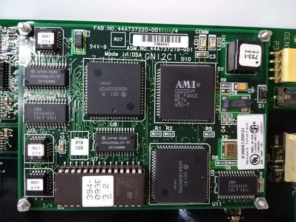
Hardware Architecture & Under-the-Hood Logic
The DS200ADGIH1AAA uses multiplexed ADC architecture to convert multiple analog inputs to digital values. Input signals pass through isolation barriers and filters before being digitized. A microcontroller manages channel sequencing, data conversion, and communication with the turbine control CPU via the VME backplane. Calibration data stored in EEPROM provides automatic correction.
Signal flow:
- Analog signals (4-20 mA, voltage, TC, RTD) connected to terminal block
- Signals pass through isolation barriers
- Front-end amplifiers condition signals to ADC range
- MUX selects channel for conversion
- ADC converts analog signal to digital value
- Microcontroller applies calibration and linearization
- Digital data buffered for VME backplane access
- Control CPU reads converted values via backplane
- Diagnostics monitor channel health and fault conditions
DS200ADGIH1AAA
Field Service Pitfalls: What Rookies Get Wrong
Channel misconfiguration causes wrong reading typeBoard defaults to 4-20 mA on all channels. I’ve seen technicians connect voltage inputs to default-configured channels, reading zero or full scale regardless of actual voltage.
- Field Rule: Verify each channel configuration matches the connected signal type (4-20 mA, 0-10 VDC, TC/RTD). Document channel assignments during commissioning. Test each channel with a known signal source to verify configuration. Re-verify configuration after board replacement or firmware upgrade.
Ground loops and common mode voltageMultiple ground references corrupt low-level signals. I’ve seen TC inputs reading 50-100°F high due to ground loops between the TC and control panel.
- Field Rule: Ground the shield at the cabinet end only. Never ground both ends. For TC/RTD inputs, use isolated TC blocks if ground loops persist. Measure ground potential between field device and control room—should be less than 1 VAC. Document grounding configuration. Use signal isolators for problematic channels.
Forgotten to account for shunt resistor for 4-20 mA4-20 mA requires a shunt resistor for voltage measurement. I’ve seen technicians connecting 4-20 mA directly to voltage-configured channels, resulting in zero reading or blown protection fuses.
- Field Rule: For 4-20 mA inputs, ensure channel is configured for current mode with internal 250-ohm shunt. Verify configuration via software tool or DIP switches. Test with a 4-20 mA calibrator—set 12 mA, verify channel reads 50% of span. Document shunt resistor value and test results.
Wiring errors cause channel damageReversing polarity or applying overvoltage destroys inputs. I’ve seen technicians wire 24 VDC to 4-20 mA channels, blowing input protection components.
- Field Rule: Verify polarity and voltage levels before wiring. Use a multimeter to test the field signal before connecting to the board. Never apply voltage above the input rating. Install fuses or protection devices for critical inputs. Document input ratings and protection schemes. Test channels after wiring with known signal sources.
Improper TC/RTD extension wire causes errorsUsing standard wire for TCs creates thermocouple junctions at terminals. I’ve seen technicians using copper wire for Type K thermocouples, introducing junction errors up to 30°F.
- Field Rule: Use TC extension wire matching the thermocouple type (Type J uses JX wire, Type K uses KX wire). For RTDs, use 3-wire or 4-wire copper wire matched for resistance. Verify wire polarity (TC red is negative). Test TC inputs with a known temperature source to verify accuracy. Document wire type and test results.
Ignoring channel diagnostics leads to missed faultsBoard provides fault codes for each channel. I’ve seen technicians ignore “sensor fault” LEDs, resulting in incorrect turbine trips or missed alarms until catastrophic failure.
- Field Rule: Monitor channel fault LEDs during operation. Use diagnostic software to read fault codes weekly or monthly. Investigate any “sensor fault” or “out of range” warnings immediately. Document fault codes and corrective actions. Replace boards with recurring channel faults.
Hot-swapping without proper procedure damages the boardRemoving the board while powered can damage components. I’ve seen technicians pull boards live to troubleshoot, causing blown components or backplane damage.
- Field Rule: Follow proper shutdown procedures before removing any Mark V board. Place the turbine in a safe state (minimum safe flame or shutdown). De-energize the control cabinet or rack before board removal. Never hot-swap analog input boards—use proper lockout/tagout procedures. Document shutdown procedures and train all technicians.
Forgotten to verify calibration after replacementBoards ship with factory calibration. I’ve seen technicians install replacement boards without verifying calibration, resulting in turbine control errors or trips.
- Field Rule: Perform a 5-point calibration on all critical channels after board replacement using a calibrated signal source. Document calibration points and measured values. Apply any correction factors if readings deviate from spec. Re-verify calibration after firmware upgrades. Maintain calibration records per plant QA requirements.
Incorrect filtering setting causes signal noiseFilter bandwidth too wide allows noise; too narrow causes slow response. I’ve seen technicians using 50 Hz filtering on 60 Hz systems, causing noisy readings.
- Field Rule: Set filter frequency appropriate to your application (10-20 Hz typical for turbine control). Verify power line frequency (50 Hz vs 60 Hz) and set filter accordingly. Test with a step input to verify response time—too slow indicates filter bandwidth too narrow. Document filter settings and response time tests.
Terminal block loose connections cause intermittent signalsVibration causes terminal screws to loosen. I’ve seen intermittent turbine trips traceable to loose terminal screws on the input board.
- Field Rule: Torque all terminal screws to manufacturer specification (typically 8-10 in-lbs). Re-torque after initial heat cycle (24 hours). Schedule periodic re-torque (monthly or per plant maintenance). Use a calibrated torque wrench. Document torque values and re-torque schedule.
Commercial Availability & Pricing Note
Please note: The listed price is for reference only and is not binding. Final pricing and terms are subject to negotiation based on current market conditions and availability.


