


Description
Hard-Numbers: Technical Specifications
- Network Protocol: ARCNET (Attached Resource Computer Network)
- Data Rate: 2.5 Mbps standard
- Network Topology: Bus, Star, or Distributed Star
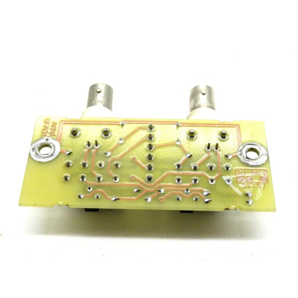
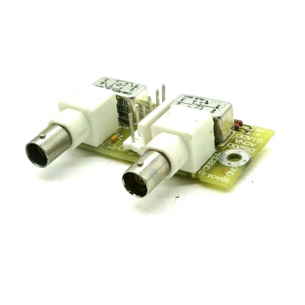
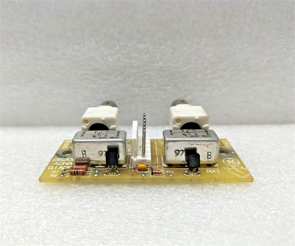
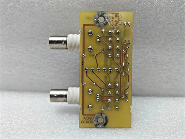
- Connector Type: BNC coaxial connector (RG-62 coaxial cable)
- Backplane Interface: VME-style 96-pin DIN connector
- Node Addressing: Rotary DIP switches (0-255)
- Bus Length: Up to 2,000 ft (610 m) with repeaters
- Nodes per Network: Up to 255 nodes
- Power Requirements: +5 VDC @ 2.5 A, +15 VDC @ 0.2 A
- Operating Temperature: 0°C to 55°C (32°F to 131°F)
- LED Indicators: Power, TX (Transmit), RX (Receive), Collision
- Diagnostic Capabilities: On-board diagnostics via LEDs and software tools
- Compatible Systems: GE Speedtronic Mark V, Mark VI with adapter
- Firmware: Factory loaded, field upgradeable via EPROM

DS200ACNAG1ADD
The Real-World Problem It Solves
Turbine control requires real-time data exchange between controllers. The DS200ACNAG1ADD provides ARCNET communication, enabling high-speed, deterministic data transmission for critical turbine control functions.
Where you’ll typically find it:
- GE gas and steam turbine control systems (Mark V)
- Generator excitation and protection panels
- Turbine auxiliary control systems
- Retrofitted turbine control applications
Bottom line: Critical communication backbone for GE turbine control systems.
Hardware Architecture & Under-the-Hood Logic
The DS200ACNAG1ADD uses an ARCNET controller chip (COM90C65 or equivalent) to handle network communication. The board interfaces with the turbine control CPU via the VME backplane, exchanging control and status data. ARCNET uses token-passing protocol for deterministic access, ensuring predictable latency. The board includes termination and bias resistors for network stub configuration.
Signal flow:
- VME backplane provides power and data interface to control CPU
- CPU writes data to ARCNET board memory buffers
- ARCNET controller encapsulates data into ARCNET frames
- Data transmitted via BNC connector to coaxial network
- Token-passing protocol ensures deterministic access
- Data received from network and buffered in memory
- CPU reads received data via VME backplane interface
- LEDs indicate power, transmit, receive, and collision status

DS200ACNAG1ADD
Field Service Pitfalls: What Rookies Get Wrong
Duplicate node addresses cause network lockupARCNET requires unique addresses. I’ve seen technicians copy DIP switch settings from another board, causing network crashes as nodes fight for the token.
- Field Rule: Verify node address is unique before powering up the board. Document the node address assignment for the entire network. Use an ARCNET network analyzer to detect address conflicts before bringing the turbine online. Re-verify addresses after any board replacement or network modification. Never duplicate addresses, even for temporary testing.
Improper termination causes signal reflectionsARCNET networks require termination at both ends. I’ve seen technicians forget termination resistors or install them at the wrong locations, causing CRC errors and intermittent communication failures.
- Field Rule: Install 93-ohm termination resistors at both physical ends of the network only. Never terminate mid-network nodes. Verify termination resistance with a multimeter—should read 93 ohms ±10% between shield and center conductor at the network ends. Document termination locations and resistance values. Replace any damaged or out-of-spec terminators.
RG-62 coaxial cable damage causes intermittent failuresCable kinks or crushed sections create impedance mismatches. I’ve seen network issues traceable to cables crushed during construction or retrofitted with RG-58 (50-ohm) instead of RG-62 (93-ohm).
- Field Rule: Use only RG-62 A/U coaxial cable for ARCNET. Never substitute with RG-58 or RG-59. Inspect cables for kinks, crush damage, or corrosion. Test cable impedance with a TDR or time-domain reflectometer—should be 93 ohms ±10%. Replace any damaged or out-of-spec cable sections. Document cable type and impedance test results.
BNC connector corrosion causes signal lossHarsh environments corrode BNC connectors. I’ve seen communication failures traceable to corroded center pins or shield connections on outdoor or humid installations.
- Field Rule: Use weatherproof BNC connectors for outdoor applications. Apply dielectric grease to connector threads to prevent corrosion. Inspect connectors during routine maintenance—look for green corrosion or white powdery deposits. Clean corroded contacts with contact cleaner and replace if severely corroded. Document connector condition and replacement intervals.
Forgotten to verify DIP switch settings after replacementDIP switches configure node address and options. I’ve seen technicians leave default settings after board replacement, causing address conflicts or communication failures.
- Field Rule: Verify DIP switch settings match the replaced board’s configuration. Document the switch settings before removing the old board. Configure node address first, then verify other options (baud rate, mode settings). Test communication after configuration—LEDs should show TX/RX activity. Document new board settings and test results.
Hot-swapping without proper procedure damages the boardRemoving the board while powered can damage components. I’ve seen technicians pull boards live to test communication, causing blown components or backplane damage.
- Field Rule: Follow proper shutdown procedures before removing any Mark V board. Place the turbine in a safe state (minimum safe flame or shutdown). De-energize the control cabinet or rack before board removal. Never hot-swap ARCNET boards—use proper lockout/tagout procedures. Document shutdown procedures and train all technicians.
Ignoring LED indicators delays fault diagnosisLEDs provide real-time status. I’ve seen technicians ignore flashing collision LEDs, missing network congestion or configuration errors until the turbine tripped.
- Field Rule: Monitor LED indicators during normal operation—Power (solid green), TX (flashing during data transmission), RX (flashing during data reception), Collision (should not flash on healthy network). Document normal LED patterns. Any deviation from normal patterns indicates a problem—investigate immediately. Use LED status to narrow down communication faults.
Grounding issues cause intermittent communication noiseImproper grounding creates ground loops and noise. I’ve seen communication failures traceable to floating racks or missing ground bonds between cabinets.
- Field Rule: Ground all cabinets to the same earth ground. Verify ground continuity between cabinets—should be less than 1 ohm. Never ground the coaxial cable shield at multiple points. Ground the shield at a single point only (typically at the central hub or termination). Document grounding configuration and test results. Use isolation transformers if ground loops persist.
Firmware mismatch causes incompatibilityDifferent firmware versions may not communicate properly. I’ve seen technicians upgrade one board without checking compatibility, causing network segmentation.
- Field Rule: Verify firmware version matches other network nodes before upgrades. Document firmware versions for all boards. Test upgraded boards in a non-critical environment before production deployment. Maintain a backup of working firmware images. Document firmware upgrade procedures and compatibility matrix.
Commercial Availability & Pricing Note
Please note: The listed price is for reference only and is not binding. Final pricing and terms are subject to negotiation based on current market conditions and availability.


