
Description
Key Technical Specifications
-
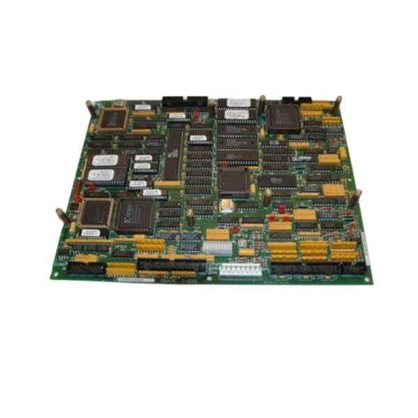
Model Number: DS2000CPCAG1A
-
Manufacturer: GE (General Electric)
-
Function: Contactor pilot board—low-power driver for external HV contactor coils
-
Connectors:
-
1 × 12-pin header (logic/command)
-
2 × 2-pin headers (coil feeds / interlocks)
-
4 × terminal blocks, max 12 field wires total
-
-
Logic Voltage: 24 VDC (coil drive derived from MARK V control power)
-
Weight: 0.25 lbs (≈ 113 g)
-
Mounting: Standard GE drive card rails; captive screws & stand-offs
-
Isolation: Basic insulation between 24 V logic and external contactor coils (user must fuse coil supply)
-
Environment: 0 – 55 °C operating (typical MARK V cubicle)
-
Status: Discontinued by OEM; new-old-stock & refurbished units available

DS2000CPCAG1A
Field Application & Problem Solved
MARK V drive cubicles still use big contactors to bring the blower motor, reactor, or compressor on-line. The DS2000CPCAG1A sits between the micro and the coil: 24 V logic from the control CPU lands on the 12-pin header, the board switches 24 V out through the terminal blocks, and the external contactor coil pulls in. When the coil shorts or the field wiring opens, the pilot card’s low-current driver survives and the front-panel LEDs tell you which leg failed—no need to meter the 480 V side.
MARK V drive cubicles still use big contactors to bring the blower motor, reactor, or compressor on-line. The DS2000CPCAG1A sits between the micro and the coil: 24 V logic from the control CPU lands on the 12-pin header, the board switches 24 V out through the terminal blocks, and the external contactor coil pulls in. When the coil shorts or the field wiring opens, the pilot card’s low-current driver survives and the front-panel LEDs tell you which leg failed—no need to meter the 480 V side.
I’ve swapped this exact card in a coal-mill exhauster drive: contactor chatter at start-up, LEDs showed open-coil on TB-2. Re-terminated the field wire, coil pulled in, mill rolled on—saved a 2 a.m. call-out.
Core value: a cheap, replaceable fuse-link between the micro and the big contactor—so the CPU lives even when the coil dies.
Installation & Maintenance Pitfalls (Expert Tips)
Terminal-block torque is 5 lb-in
Over-torque and the phenolic cracks; under-torque and the 24 V contactor feed arcs. Hit it with a calibrated screwdriver and visually check for cracks—saves a second trip.
Over-torque and the phenolic cracks; under-torque and the 24 V contactor feed arcs. Hit it with a calibrated screwdriver and visually check for cracks—saves a second trip.
Coil supply must be externally fused
The board driver is rated for contactor in-rush, not a dead short. Fuse the 24 V coil feed at 2 A or you’ll blow the PCB trace when the coil shorts—then you’re chasing “no output” instead of “bad coil.”
The board driver is rated for contactor in-rush, not a dead short. Fuse the 24 V coil feed at 2 A or you’ll blow the PCB trace when the coil shorts—then you’re chasing “no output” instead of “bad coil.”
12-pin header is keyed—don’t force it
The header will accept a plug 180° out. Pin-1 is marked with a white dot—line it up or the CPU sees 24 V on a logic return and faults the whole rack.
The header will accept a plug 180° out. Pin-1 is marked with a white dot—line it up or the CPU sees 24 V on a logic return and faults the whole rack.
LEDs only show logic side
Green LED = driver is trying; it does not prove the contactor moved. For safety-critical loops, loop the auxiliary contact back to a separate input card and prove the contactor actually lifted.
Green LED = driver is trying; it does not prove the contactor moved. For safety-critical loops, loop the auxiliary contact back to a separate input card and prove the contactor actually lifted.


