
Description
Order Code Decoder (Critical for Installation)
The part number follows the GE 750 series order code structure:
| Position | Code | Meaning |
|---|---|---|
| Base Unit | 750 | 750 Feeder Management Relay (no autoreclose) |
| Phase Current Inputs | P5 | 5A phase current inputs (Ia, Ib, Ic) |
| Zero-Sequence Current Inputs | G5 | 5A zero-sequence current input (for ground fault protection) |
| Sensitive Ground Current Input | S5 | 5A sensitive ground current input (for high-impedance ground fault detection) |
| Control Power | HI | High range: 88-300 VDC / 70-265 VAC @ 48-62 Hz |
| Analog Outputs | A20 | Eight (8) analog outputs: 4-20 mA range |
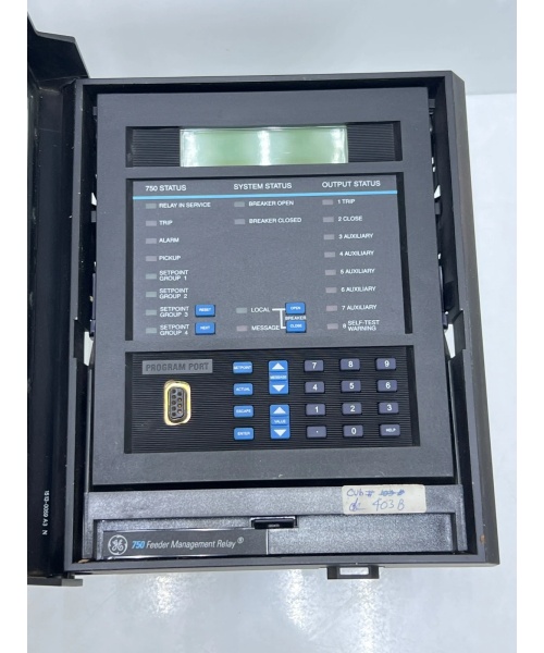
| Breaker Closed LED | R | Red LED indicator for breaker closed status |
| Display/Ethernet | (Not specified) | Enhanced display option available but not indicated in this order code |
Note: The “HI” power supply code is critical—it requires a high-voltage control source (station service 120-240VAC or 125-250VDC), NOT low-voltage battery power. Do not connect 24VDC battery to this relay—damage will occur.

GE 750-P5-G5-S5-HI-A20-R
Hard-Numbers: Technical Specifications
Power Supply & Electrical
- Control Power (HI) : 88-300 VDC / 70-265 VAC @ 48-62 Hz (nominal 25VA, max 35VA)
- Power Consumption: 25W nominal, 35W maximum
- Input Impedance (Analog) : 375Ω ±10%
- Insulation Voltage: 300V
Current & Voltage Inputs
- Phase Current Inputs (P5) : 5A three-phase (Ia, Ib, Ic)
- Ground Current Input (G5) : 5A zero-sequence current input
- Sensitive Ground Current Input (S5) : 5A sensitive ground current input
- Voltage Channels: 4 isolated voltage inputs (50-240V range per channel, up to 5000:1 VT ratio)
- Frequency Range: 40-70 Hz for protection functions
Protection Functions
- Phase Overcurrent (50P/51P) : Instantaneous and time-overcurrent with 15 curve types (ANSI, IEC, Custom FlexCurves)
- Neutral Overcurrent (50N/51N) : Instantaneous and time-overcurrent for neutral current
- Ground Overcurrent (50G/51G) : Instantaneous and time-overcurrent for zero-sequence current
- Sensitive Ground (50SG/51SG) : Instantaneous and time-overcurrent for sensitive ground detection
- Negative Sequence (50_2/51_2) : Instantaneous and time-overcurrent for negative-sequence current
- Voltage Protection: Phase undervoltage (27P), phase overvoltage (59P), neutral overvoltage (59N), negative sequence overvoltage (59_2), undervoltage auto-restoration, underfrequency/overfrequency (81U/81O)
- Directional Elements: Phase directional (67P), neutral directional (67N), ground directional (67G), sensitive ground directional (67SG)
- Additional: Voltage restrained overcurrent, breaker failure (50BF), reverse power (optional Mod 008), fault locator
Analog Outputs
- Channels: Eight (8) independent analog output channels
- Range: 4-20 mA per channel
- Applications: Metering export to SCADA/DCS (current, voltage, power, power factor, frequency, demand, analog input values)
Communications
- Serial Ports: RS232 (front panel), RS422/RS485 (rear)
- Protocols: Modbus RTU, DNP3.0 Level 2, IEC 60870-5-103
- Ethernet: Optional (10Base-T) – requires “-E” display option (not specified in this order code)
- Baud Rate: Up to 19,200 bps (serial)
Data Capture & Recording
- Event Recorder: Up to 512 events with chronological order
- Waveform Capture (Trace Memory) : 64-cycle capture at 128 samples/cycle per channel
- Data Logger: User-configurable sampling for up to 8 actual values
- Trip Counters: Records breaker trip operations
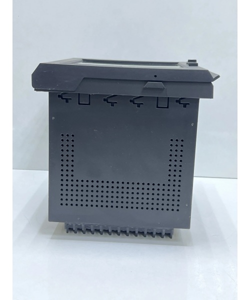
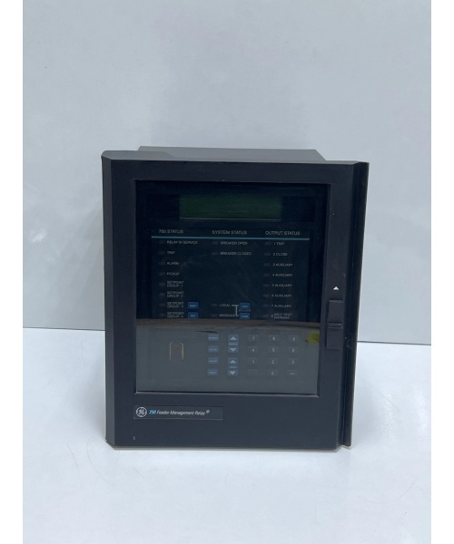
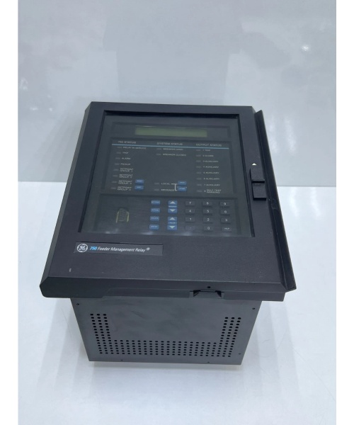
Physical & Environmental
- Dimensions: Approx. 18cm W × 16.5cm L × 21.5cm H (drawout case)
- Panel Mounting: Standard 19-inch rack, SR-series drawout construction
- Operating Temperature: -40°C to +70°C (-40°F to +158°F)
- Humidity: Up to 90% non-condensing
- Pollution Degree: II
- Ingress Protection: IP40 (front panel) with dust-protective door
- Certifications: UL listed (A3775), CE marked (IEC 60950 LVD), ISO 9001:2000 registered
Setpoint Groups
- Groups: 4 programmable setpoint groups (allows adaptive protection schemes)
The Real-World Problem It Solves
Legacy protection relays require separate metering equipment, data loggers, and analog output modules to feed SCADA systems, creating cabinet space constraints and integration complexity. The 750 series eliminates this by integrating protection, metering, data logging, and eight analog output channels into a single drawout module. Additionally, the “HI” high-voltage power supply option enables direct connection to station service AC or DC bus, eliminating the need for separate DC power supplies in substations where 125VDC/120VAC control power is readily available.
Where you’ll typically find it:
- Medium voltage switchgear in utility substations (13.8kV-69kV distribution feeders)
- Industrial plant distribution systems requiring comprehensive protection and analog output integration
- Bus protection schemes where voltage inputs and multiple protection functions are needed
- Transformer backup protection where voltage-restrained overcurrent and directional elements are required
- Legacy substation retrofits replacing older electromechanical relays (GE MIF/MIF II, Multilin 239, 735/737)
This relay provides a complete protection and metering solution in a single chassis, reducing wiring complexity, cabinet space requirements, and overall system cost while enhancing diagnostic and troubleshooting capabilities through advanced event recording and waveform capture.
GE 750-P5-G5-S5-HI-A20-R
Hardware Architecture & Under-the-Hood Logic
The 750 series uses a dual-processor architecture:
-
Measurement Processor: Motorola 68332 32-bit microprocessor handles all analog signal acquisition (current/voltage inputs), logic inputs, and output relay control. This processor samples AC inputs through 400Hz anti-aliasing filters and calculates RMS values, symmetrical components, phasors, and frequency at up to 128 samples per cycle.
-
Communications/Display Processor: Grid Connect DSTni-LX Turbo 186 16-bit microprocessor manages user interface (front panel LCD display, keypad), communications ports (RS232/RS485, optional Ethernet), and data storage (event recorder, trace memory, data logger).
Internal signal flow:
- Analog Acquisition: Phase current, neutral current, ground current, sensitive ground current, and voltage inputs pass through isolation transformers and anti-aliasing filters to dual 16-bit ADCs
- Signal Processing: Measurement processor calculates phasors (magnitude/angle), symmetrical components (positive/negative/zero sequence), frequency, and rate-of-change
- Protection Logic: Each protection element executes once per cycle using RMS values—timing is independent of system frequency
- Analog Output Mapping: Up to 8 channels can be mapped to any measured value (current, voltage, power, demand, power factor, frequency, analog input) and scaled to 4-20mA range
- Event & Waveform Recording: Fault events trigger capture of 64-cycle waveforms at 128 samples/cycle per channel, plus contextual event data
- Communications Processing: Communication processor serves Modbus/DNP/IEC 60870 data maps and manages Ethernet/serial protocols
- Self-Diagnostics: Continuous self-test monitors internal power, memory integrity, ADC references, and processor health, forcing Self-Test Warning relay if fault detected
Field Service Pitfalls: What Rookies Get Wrong
Misinterpreting the “HI” Power Supply Code
The “HI” in the order code indicates high-voltage control power (88-300VDC / 70-265VAC), not “high current” or “high impedance.” Rookies often assume all GE relays use 24VDC battery power and attempt to connect this relay to a 24V station battery, which will not power up the relay and may damage the internal power supply. I’ve responded to emergency calls where technicians spent hours troubleshooting a “dead” relay only to discover they were feeding it 24VDC instead of the required 125VDC station service.
- Field Rule: Verify the power supply code in the order code before wiring control power. “HI” = 88-300VDC or 70-265VAC. “LO” = 20-60VDC or 20-48VAC. Never connect 24VDC to an “HI” relay. Measure the available control power at the cabinet with a multimeter before energizing the relay.
Confusing Ground (G5) and Sensitive Ground (S5) Current Inputs
The 750 series has two separate ground current inputs: G5 (5A zero-sequence current input) and S5 (5A sensitive ground current input). Rookies often wire a single core-balance CT or window CT to both inputs, or connect a CT designed for sensitive ground detection to the zero-sequence input, resulting in incorrect pickup settings and protection blocking. These inputs are mutually exclusive in many applications and serve different protection schemes.
- Field Rule:
- G5 Input: Connect to standard zero-sequence CT (toroidal/core-balance CT) with 5A secondary rating for ground fault protection (51G/50G, 67G)
- S5 Input: Connect to sensitive ground CT (high-impedance or window CT) for high-impedance ground fault detection (51SG/50SG, 67SG)
- Verify the protection function setpoint configuration to confirm which input each ground element is using
- Use twisted-pair shielded cable for zero-sequence CT connections per the instruction manual to prevent noise pickup
Overlooking the Red Breaker LED (R) Option
The “R” in the order code specifies a red LED indicator for breaker closed status, not “Relay” or “Reset.” Rookies misinterpret this as indicating a relay type or output configuration, missing the important detail that the front panel includes a dedicated breaker status indicator. This LED provides immediate visual confirmation of breaker position without needing to access the rear terminal or display menu.
- Field Rule: Locate the red LED on the front panel labeled “BREAKER CLOSED” or similar. Verify it illuminates when the breaker is in the closed position and extinguishes when the breaker is open or tripped. Use this indicator during commissioning to confirm breaker status monitoring is wired correctly before finalizing protection settings.
Neglecting to Map Analog Outputs to Measured Values
The 750 series includes eight 4-20mA analog output channels (A20 option), but these must be explicitly mapped to measured values through the setpoint menus. Rookies assume the analog outputs automatically export current/voltage values to SCADA, only to find the channels outputting 0mA or fixed values regardless of system conditions. Each channel must be configured for source, scaling, and range.
- Field Rule: Access the S6 MONITORING > ANALOG OUTPUTS menu in EnerVista 750 Setup software or front panel:
- For each of the 8 channels (Output 1-8), select the measured value source (e.g., Phase A Current, Phase A Voltage, Real Power, Reactive Power, Power Factor, Frequency)
- Configure the scaling (minimum/maximum primary engineering values)
- Verify the 4-20mA output with a multimeter at the terminal block during commissioning
- Confirm the SCADA system receives correct values at both low and high operating points
Forgetting the 4 Setpoint Groups Feature
The 750 series supports 4 programmable setpoint groups, allowing adaptive protection schemes for different system configurations (e.g., normal operation, transfer condition, maintenance mode). Rookies often configure only one setpoint group and manually change settings when system configuration changes, increasing the risk of human error during switching operations.
- Field Rule:
- Configure all 4 setpoint groups for different operating conditions (e.g., Group 1 = normal, Group 2 = transfer, Group 3 = maintenance, Group 4 = emergency)
- Assign logic inputs or virtual inputs to trigger setpoint group changes automatically
- Verify setpoint group activation through the front panel display (A1 STATUS menu shows active group number)
- Document which group corresponds to each operating condition in the commissioning report
Commercial Availability & Pricing Note
Please note: The listed price is for reference only and is not binding. Final pricing and terms are subject to negotiation based on current market conditions and availability.


