
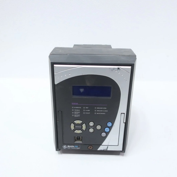
Description
Hard-Numbers: Technical Specifications
- Current Inputs: 5A three-phase (Ia, Ib, Ic), 5A ground current input (Ig), 1A sensitive ground input (optional)
- Voltage Inputs: Up to 4 channels for bus voltage (Va, Vb, Vc, Vn), plus auxiliary VT
- Power Supply: Low voltage option 24-48 VDC (20-60 VDC operating range), 125-250 VDC / 120-240 VAC standard option also available
- Communication Ports: Standard RS485 rear (Modbus RTU/DNP3.0/IEC 60870-5-103), optional Ethernet copper & fiber with IEC 61850 GOOSE/Modbus TCP/DNP3.0/IEC 60870-5-104
- Protection Functions: Phase/neutral/ground time overcurrent (51P/51N/51G), instantaneous overcurrent (50P/50G/50N), thermal overload (49), directional overcurrent (67P/67N/67G)
- Voltage Protection: Undervoltage (27P, 27X), overvoltage (59P, 59N, 59X, 59_2), over/under frequency (81O, 81U), volts-per-hertz (24)
- Digital I/O: Up to 10 contact inputs, 7 outputs (2 Form A trip/close, 5 Form C auxiliary)
- Operating Temperature: -40°C to +60°C
- Storage Temperature: -40°C to +85°C
- Isolation Rating: 2.5 kV AC dielectric strength (typical for 350 series)
- Power Consumption: ~15W nominal, 20W maximum
- Dimensions: Standard 350 form factor (H7.93″ × W6.62″ × D9.62″ approx., varies by case design)
- Weight: 4-5 kg (9-11 lbs) gross
- Certifications: cULus, CE compliant
- MTBF: Typically >100,000 hours for 350 series relays

GE 350-L-PX-GX-H-E-N-N-V-SN-N-N
The Real-World Problem It Solves
Substations and switchgear rooms often lack a dedicated 24V DC control source for protection relays, forcing engineers to derive control power from expensive 120/240V AC station service or add external DC power supplies. This creates cabinet space constraints and introduces potential single points of failure. The 350-L-PX-GX series with low voltage power option eliminates this headache by operating directly from the 24V DC battery systems already present for breaker trip coils and DC control circuits, reducing wiring complexity and improving reliability.
Where you’ll typically find it:
- Industrial plants with 24V DC control power infrastructure (substations, motor control centers)
- Utility substations where space is at a premium and low-voltage operation simplifies design
- Retrofit projects replacing older electromechanical relays in 24V DC environments
- Process plants where the protection relay must ride through battery backup during AC power loss
This relay keeps critical feeders online by drawing control power from the same source as the breaker mechanism, ensuring protection remains active even when station service AC is lost—a fundamental requirement for safety and reliability in any industrial facility.
Hardware Architecture & Under-the-Hood Logic
The 350 series uses dual 32-bit Freescale MPC5554 microprocessors for redundant measurement and control: the primary processor handles all analog measurements (currents, voltages) and digital inputs, while the secondary manages output relays and protection logic. This architecture ensures that measurement accuracy and response speed are maintained even during intensive computation. The module communicates with the backplane through a high-speed internal bus and features isolated input transformers for all analog channels to provide robust noise immunity and ensure safe operation even with ground reference shifts. Protection elements execute on fixed scan cycles with configurable time-current curves (ANSI, IEC, user-definable FlexCurve), and the watchdog circuit continuously monitors relay health, forcing critical failure relay (Output #7) to drop if internal fault detected.
Internal signal flow:
- Analog Acquisition: Current transformers and voltage transformers feed isolated signals to dual 16-bit ADCs for RMS calculation
- Sequence Component Processing: Microprocessor calculates symmetrical components (positive/negative/zero sequence) from raw phase data
- Protection Element Evaluation: Each protection function (overcurrent, voltage, frequency, directional) compares measured values against setpoints and determines operate/don’t-operate states
- Logic Engine: Sixteen programmable logic elements (FlexLogic) allow custom interlocking, breaker control schemes, and cross-tripping via virtual inputs
- Output Relay Control: When trip condition detected, processor energizes appropriate output relay (Trip, Close, or auxiliary) with <8 ms operate time
- Communication Processing: Simultaneously updates SCADA/DCS via Modbus/DNP/IEC 61850 with synchronized timestamping and event logging
- Self-Diagnostics: Continuous self-test cycles monitor memory integrity, internal power rails, ADC reference voltages, and watchdog timer status
- Status Reporting: Front-panel LCD, 12 programmable LEDs, and critical failure relay report current state to operators
GE 350-L-PX-GX-H-E-N-N-V-SN-N-N
Field Service Pitfalls: What Rookies Get Wrong
Misinterpreting the “PX” and “GX” Placeholder Codes
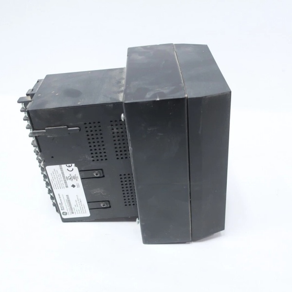
The part number 350-L-PX-GX contains placeholder codes in the phase current and ground current positions. “PX” and “GX” are not actual protection functions—they’re manufacturing placeholders filled during ordering with specific options like P0 (no phase CTs), P5 (5A CTs), or G5 (5A ground CT). I’ve seen techs order relays expecting specific CT input configurations only to receive a base unit with no current inputs installed. Always verify the actual option codes on the nameplate label (after the “350-” prefix) before assuming capabilities.
- Field Rule: Read the full order code string from the side panel label. The format is always
350-[P/G][I/P][G][0/1/5/X][H/L/A][E/M/S][...where each character has meaning. Never rely on part numbers from purchase orders or quote documents alone—always cross-check against the physical unit installed in the cabinet.
Applying 24V DC Power Without Polarity Consideration
The low voltage power option (24-48 VDC) simplifies control power wiring, but it introduces a common failure mode: reverse polarity connection. Unlike AC power which is less sensitive to polarity reversal, connecting +24V DC to the relay’s negative terminal or vice versa will not immediately destroy the relay due to internal protection diodes, but it will prevent the relay from powering up and can cause confusion about whether the relay is failed or simply miswired. I’ve responded to service calls only to find the DC input terminals swapped.
- Quick Fix: Use a multimeter in continuity or diode test mode to verify polarity before applying power. Connect the positive (+) lead to the terminal marked with “+” or with the red indicator light if present, and negative (-) to the opposite terminal. Double-check connections against the wiring diagram on the inside cover of the relay.
Overlooking Ground CT Connection Requirements
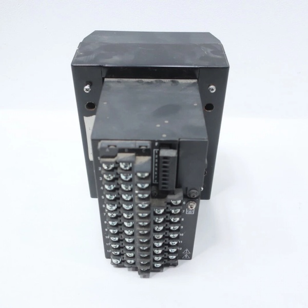
The 350 series with “5” ground current inputs requires external ground CT wiring for sensitive ground fault detection. Rookies often assume the relay automatically derives ground current from the residual sum of phase CTs or connect the ground CT in parallel with the phase CTs, which will cause incorrect current measurement and potential protection element blocking during fault conditions. The ground CT must be connected to a dedicated terminal pair specifically designated for ground/sensitive ground input.
- Field Rule: Connect the ground CT secondary to the ground current input terminals (labeled on the terminal block as Ig or Isg) using the correct CT ratio and burden specifications per the protection setting. Never wire the ground CT to the same terminals as phase CTs. Verify the ground CT orientation (polarity) matches the directional element settings during commissioning.
Assuming “SN” Communication Means No Ethernet
The “SN” code in the communications position typically indicates standard communications (RS485 + front USB), but I’ve seen techs assume this means “Serial Only” and neglect to configure Ethernet settings or install fiber optic modules when the station requires Ethernet/IEC 61850 connectivity for SCADA integration. The 350 series supports both serial and Ethernet simultaneously—they’re not mutually exclusive.
- Quick Fix: Check the rear panel for Ethernet port presence. If fiber or copper Ethernet is required for IEC 61850 GOOSE messaging or high-speed Modbus TCP/IP, ensure an optional communications daughter board (indicated by “3E”, “2E”, or similar code in the part number) is installed. Configure IP address, subnet, and protocol settings in S1 RELAY SETUP > COMMUNICATIONS menu. Do not assume “SN” precludes Ethernet capability.
Commercial Availability & Pricing Note
Please note: The listed price is for reference only and is not binding. Final pricing and terms are subject to negotiation based on current market conditions and availability.


