
Description
Hard-Numbers: Technical Specifications
- Sensor Input: Pt100 RTD (3-wire or 4-wire), Pt1000 RTD, Thermocouple Type J/K/T/E
- Output Signal: 4-20 mA (2-wire loop-powered)
- Communication: HART Protocol (digital superimposed on 4-20 mA)
- Accuracy: ±0.1°C (RTD), ±1.0°C (Thermocouple)
- Supply Voltage: 10-35 VDC
- Load Resistance: 0-750 Ω @ 24 VDC
- Temperature Range: Dependent on sensor (RTD: -200°C to 850°C, TC: -200°C to 1200°C)
- Input Type: Selectable via configuration
- Electrical Connection: Terminal block (screw or spring clamp)
- Mounting Type: DIN 43729 head-mount (B-head connection head)
- Operating Temperature: -40°C to 85°C (-40°F to 185°F)
- Environmental Protection: IP00 (for use inside connection head)
- Sensor Burnout Detection: Configurable ( upscale or downscale)
- Cold Junction Compensation: Built-in (for thermocouples)
- Diagnostics: Sensor fault, loop fault, overrange alarm

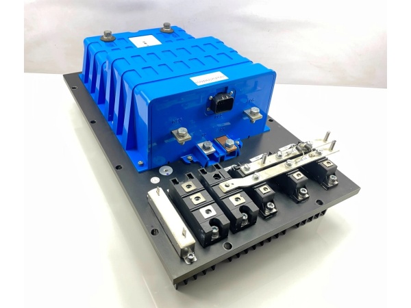
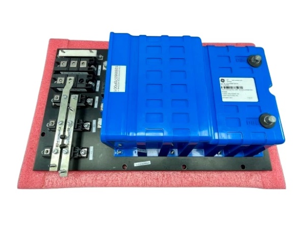
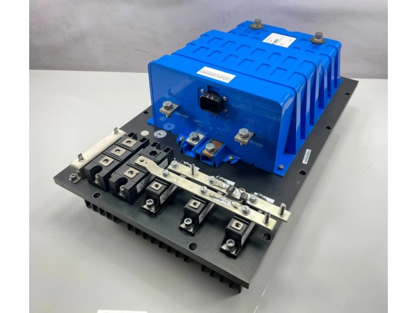
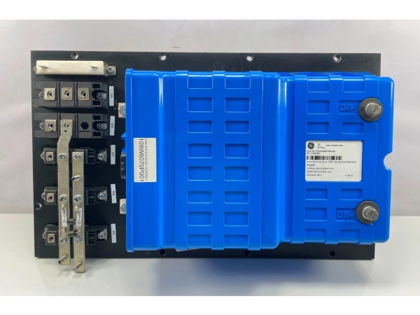
GE 151X1233DB01SA01R
The Real-World Problem It Solves
Long RTD/TC cable runs cause signal loss and noise. The 156A1227P009 converts sensor signals to 4-20mA at the source, eliminating voltage drop errors and providing HART diagnostics for predictive maintenance.
Where you’ll typically find it:
- Connection heads on temperature sensors in process lines
- Reactor and vessel temperature monitoring
- Heat exchanger temperature measurement
- HVAC and utility temperature loops
Bottom line: Converts sensor signals to robust 4-20mA with linearization and diagnostics.
Hardware Architecture & Under-the-Hood Logic
This transmitter receives millivolt or resistance signals from temperature sensors (RTD/TC). An internal ADC converts analog sensor signals to digital values. A microcontroller applies linearization algorithms (Callendar-Van Dusen for RTD, polynomial for TC) to convert raw values to temperature. The 4-20 mA output driver generates a current proportional to temperature. HART modem superimposes digital communication on the analog loop. Non-volatile memory stores calibration and configuration.
Signal flow:
- RTD/TC sensor connected to transmitter input terminals
- ADC converts sensor signal to digital value
- Microcontroller applies linearization and cold junction compensation (TC)
- Temperature converted to 4-20 mA via DAC
- Current loop driver outputs 4-20 mA proportional to temperature
- HART modem adds FSK digital signal to analog loop
- Output terminals deliver 4-20 mA + HART to DCS/PLC
- Diagnostics monitor sensor health and loop integrity
Field Service Pitfalls: What Rookies Get Wrong
3-wire RTD wired as 2-wire causes compensation errorsLead resistance compensation fails with incorrect wiring. I’ve seen technicians jumper the 3-wire connection as 2-wire, causing temperature errors up to 3-5°C on long cable runs.
- Field Rule: Verify 3-wire RTD wiring: A (white) to +, B (red) to -, C (white) to compensation terminal. Never jumper the compensation terminal to another wire. Measure lead resistance on each wire—all three should match within 0.5 ohms. Document wiring configuration and lead resistance. For long runs (>500 ft), use 4-wire RTD for best accuracy.
Thermocouple polarity reversed causes negative temperature readingThermocouple red lead is negative in US standard. I’ve seen technicians wire red to positive terminal, causing the transmitter to read negative temperature at ambient conditions.
- Field Rule: Verify thermocouple polarity: Red lead to negative (-) terminal, Yellow/Blue/White (depending on type) to positive (+) terminal. Test with a known temperature source (ice bath or handheld calibrator). If reading is negative at room temperature, polarity is reversed. Document thermocouple type and polarity in your configuration records.
Ground loops and common mode voltageMultiple ground references create current loops that corrupt the 4-20 mA signal. I’ve seen technicians ground both the sensor shield and the transmitter housing to different grounds, causing drift of 1-2 mA.
- Field Rule: Ground the shield at the DCS/PLC cabinet only. Never ground both ends. Ground the transmitter housing to the same earth ground as the connection head. Measure ground potential between field device and control room—should be less than 1 VAC. If ground loops persist, install a signal isolator between transmitter and control system.
Forgotten to configure sensor type in transmitterTransmitter defaults to Pt100. I’ve seen technicians leave the default configuration with a thermocouple connected, resulting in incorrect readings or sensor fault alarms.
- Field Rule: Configure the transmitter for the correct sensor type (Pt100, Pt1000, Type J/K/T/E) during commissioning. Test with a known temperature source to verify linearization is correct. Document sensor type and configuration in your commissioning records. Re-verify configuration after any maintenance or sensor replacement.
Improper grounding of HART communicatorHandheld HART communicators require proper grounding. I’ve seen technicians float the communicator, causing communication failures and potentially damaging the device.
- Field Rule: Connect the HART communicator ground terminal to the same earth ground as the control system. Never float the communicator. Use a ground strap or earth ground connection. Test HART communication by reading a known parameter (e.g., PV, URV, LRV). If communication fails, verify all connections and ground continuity.
Incorrect sensor burnout configuration causes confusionBurnout detection alarms when sensor fails. I’ve seen technicians configure upscale burnout on safety-critical temperature loops, causing the system to read high temperature when the sensor fails, potentially masking actual failures.
- Field Rule: Configure burnout direction based on safety philosophy. For safety-critical high-temperature alarms, use downscale burnout (reads low on fault). For safety-critical low-temperature alarms, use upscale burnout (reads high on fault). Document burnout configuration and safety rationale. Test burnout by disconnecting the sensor—transmitter should go to configured burnout value.
Ignoring HART diagnosticsThe transmitter provides rich diagnostic data. I’ve seen technicians ignore alarms like “sensor drift” or “cold junction fault,” leading to unexpected failures and downtime.
- Field Rule: Read HART diagnostics weekly or monthly via AMS or handheld communicator. Monitor sensor status, cold junction temperature, and electronics health. Look for warnings and alarms—address immediately, not during the next scheduled shutdown. Create a trend log of key parameters and review trends for anomalies. Replace transmitters at end-of-life or when diagnostics indicate degradation.
Commercial Availability & Pricing Note
Please note: The listed price is for reference only and is not binding. Final pricing and terms are subject to negotiation based on current market conditions and availability.


