
Description
Hard-Numbers: Technical Specifications
- Pressure Range: 10-100 psig (0.7-6.9 bar)
- Setpoint Accuracy: ±1.5% of full scale
- Deadband: 5-15% of setpoint (adjustable)
- Switch Type: SPDT form C contact
- Contact Rating: 10 A @ 250 VAC resistive; 5 A @ 125 VDC
- Process Connection: 1/4″ NPT female
- Process Material: 316 Stainless Steel or Brass (depending on fluid)
- Enclosure Rating: NEMA 4X (IP66) polycarbonate or cast aluminum
- Operating Temperature: -40°C to 85°C (-40°F to 185°F)
- Maximum Static Pressure: 500 psig (34.5 bar)
- Adjustment Type: External dial with fine-tuning screw
- Weight: 2.0 lbs (0.9 kg)
- Certifications: UL, CSA, CE, ATEX
- Mounting Orientation: Vertical or horizontal

The Real-World Problem It Solves
Overpressure damages equipment and creates safety hazards. The 151X1235DZ10PC50 monitors process pressure, triggering alarms and shutdowns before catastrophic failure occurs.
Where you’ll typically find it:
- Pump discharge pressure monitoring
- Compressor safety and shutdown systems
- Pressure vessel and tank protection
Bottom line: Mechanical pressure switch provides reliable pressure monitoring without external power.
Hardware Architecture & Under-the-Hood Logic
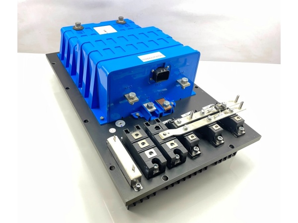
This switch uses a diaphragm or bellows sensing element that responds to pressure changes. Pressure deflection is transferred via linkage mechanism to the snap-action switch. When pressure exceeds setpoint, the mechanism trips the SPDT contacts. Deadband adjustment determines pressure required to reset contacts. No external power required for operation.
Signal flow:
- Process pressure applied to diaphragm or bellows
- Diaphragm deflects proportionally to pressure
- Diaphragm movement transmitted through linkage to switch mechanism
- Spring force resists movement until setpoint reached
- Snap-action mechanism trips when pressure overcomes spring force
- SPDT contacts change state (common to normally open or normally closed)
- Deadband adjustment determines reset pressure point
- Contacts provide discrete signal to control system or directly to load
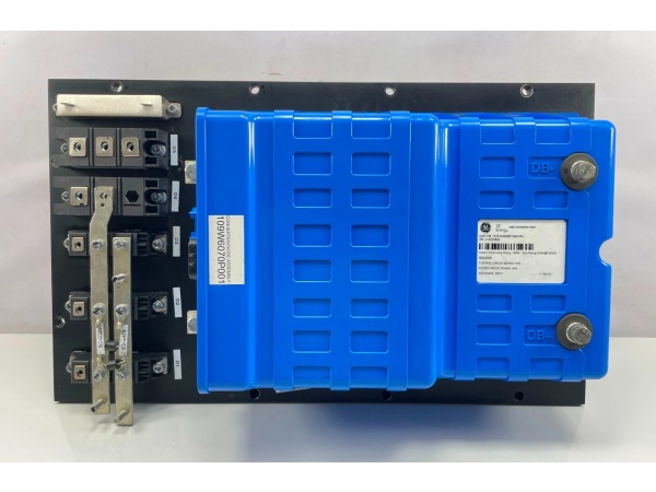
GE 151X1233DB01SA01R
Field Service Pitfalls: What Rookies Get Wrong
Over-torquing process connections damages the switchThe 1/4″ NPT threads can over-compress the diaphragm. I’ve seen technicians over-tighten with pipe wrenches, causing the diaphragm to warp and shift calibration.
- Field Rule: Use thread sealant (PTFE tape or pipe dope) and torque to 15-20 ft-lbs maximum. Never use a cheater bar. Install a pressure snubber or needle valve for high-pressure pulsating applications. If leakage occurs, do not over-tighten—check thread alignment and sealant.
Incorrect deadband causes rapid cyclingDeadband too small causes contact chatter. I’ve seen rapid cycling destroy contacts and cause nuisance alarms, leading operators to bypass safety interlocks.
- Field Rule: Set deadband to minimum 5-10% of setpoint. Test operation by slowly varying pressure—contacts should change state cleanly without bouncing. Monitor contact operation with an indicator lamp. For noisy signals, consider adding a small time delay (2-5 seconds) in your PLC logic.
Nuisance tripping from pressure spikesProcess surges cause false trips. I’ve seen technicians lower the setpoint to compensate, reducing safety margins and risking equipment damage.
- Field Rule: Install a pressure snubber to dampen pressure spikes. Set the snubber orifice size based on process characteristics (typical orifice: 0.010″ to 0.030″). Document the snubber installation and orifice size. If spikes persist, increase deadband slightly (up to 15%) but never lower the setpoint below the safe operating limit.
Ignoring wetted material compatibilitySwitch internals see process fluid. I’ve seen corrosive fluids attack brass internals, causing calibration drift and eventual failure.
- Field Rule: Verify wetted materials (316 SS or brass diaphragm) are compatible with process fluid. Check chemical compatibility charts for temperature and concentration. For aggressive chemicals, specify 316 SS construction. Document expected fluid conditions and replacement intervals. Install isolation valves for maintenance without process drainage.
Forgotten to test operation during commissioningNew switches are rarely verified. I’ve found switches shipped with setpoints at factory defaults (typically 0 psig), not application values.
- Field Rule: Test switch operation using a calibrated pressure source and gauge. Gradually increase pressure until contacts trip—record this value. Decrease pressure and record reset point. Adjust setpoint and deadband as needed. Document final values in your commissioning report. Re-test annually or per plant maintenance schedule.
Mounting orientation affects setpoint accuracyGravity affects switch mechanism on some models. I’ve seen vertical mounting causing setpoint errors up to 3%.
- Field Rule: Mount the switch with the adjustment knob accessible and visible. Refer to manufacturer’s orientation guidelines—most models can be mounted in any orientation, but horizontal with adjustment on top is preferred. Avoid mounting with process connection pointing down where fluid can accumulate. Document actual mounting orientation in your calibration records.
Forgotten to bypass during maintenanceTechnicians often forget to bypass the switch during maintenance. I’ve seen attempts to remove the switch under pressure, causing process fluid to spray and creating safety hazards.
- Field Rule: Install isolation valves and a bypass loop around the switch. Close both isolation valves before removing the switch. Verify zero pressure at the switch using a pressure gauge. Use appropriate PPE (face shield, gloves) when removing the switch. Document bypass procedures and train all technicians.
Commercial Availability & Pricing Note
Please note: The listed price is for reference only and is not binding. Final pricing and terms are subject to negotiation based on current market conditions and availability.


