
Description
Hard-Numbers: Technical Specifications
- Nominal Output Current: 35A DC continuous
- Forcing Capability: 210% of rated current (73.5A) temporary forcing
- AC Input Range: 90-280V rms, nominal (3-phase or 1-phase)
- AC Input Frequency: Up to 480 Hz
- Secondary DC Input: 125-250V DC (battery backup)
- Output Voltage: Up to 250V DC regulated (field excitation)
- PWM Switching Frequency: ~1,000 Hz
- Power Topology: IGBT-based 3-phase inverter with DC link
- Dimensions (Approximate): 40 x 45 x 35 cm
- Weight (Approximate): 8.8 kg
- Ambient Temperature: 0°C to 40°C (derating at 50°C)
- Enclosure Rating: NEMA 1/IP20 or IP21 standard (IP54 optional)
- Communication Protocols: Ethernet LAN, EGD protocol, Modbus TCP/IP
- Control Software Requirement: ControlST V07.04.00C or higher (for upgraded PCM versions)
- Isolation Rating: Per UL508C and EN 50178 for power conversion equipment

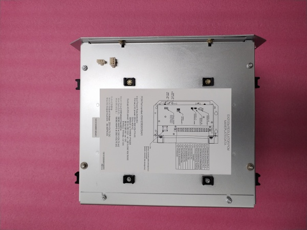
GE 151X1235DB15SA02
The Real-World Problem It Solves
Generator excitation systems need precise, fast-responding DC field current regulation to maintain stable voltage output during load transients, grid faults, and startup sequences. The 151X1235DB15SA02 provides a compact, digitally-controlled power conversion solution that converts AC input into precisely regulated DC excitation current with exceptional dynamic response and forcing capability.
Where you’ll typically find it:
- Gas turbine generators (Frame 5, Frame 6, Frame 7, Frame 9) in combined cycle and simple cycle plants
- Steam turbine generators in utility power plants and industrial cogeneration facilities
- Hydro generators in hydroelectric installations requiring precise excitation control
- EX2100e excitation control cabinets (35A simplex or warm backup configurations)
- Retrofit projects upgrading older analog excitation systems to digital control
Bottom line: It’s the power conversion heart of GE’s EX2100e digital excitation system—delivering the field current that keeps generator voltage stable under any operating condition.
Hardware Architecture & Under-the-Hood Logic
The 151X1235DB15SA02 is a sophisticated power conversion module combining IGBT-based PWM inverter technology with digital control interfaces for precise excitation control. It interfaces directly with the EX2100e Universal Controller Stand-alone (UCSB) via High-Speed Serial Link (HSSL) and does not contain its own microprocessor—all control logic resides in the UCSB.
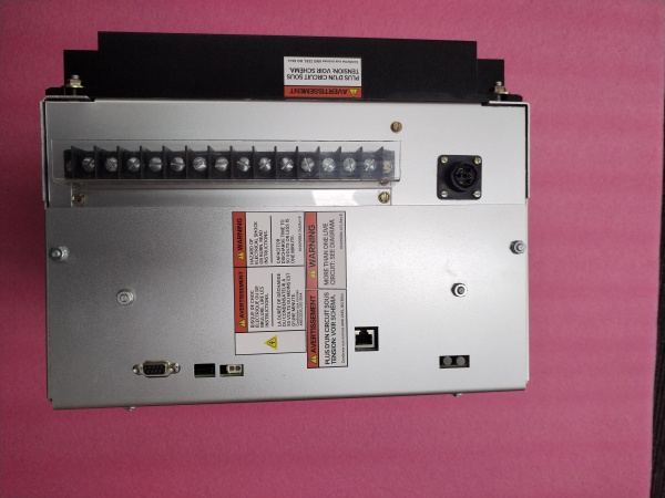
- Three-phase AC input (90-280V rms from PMG, auxiliary bus, or generator terminals) enters through input EMI filters
- Input section consists of 3-phase diode bridge rectifier with line reactors for current limiting
- DC link capacitors store energy and provide smooth DC bus voltage for IGBT inverter
- Dynamic Discharge (DD) circuit limits DC link voltage during load rejection or unit trip events
- IGBT inverter bridge (6 devices in 3-phase configuration) PWM-modulates DC link at ~1,000 Hz
- Output section feeds regulated DC to exciter field through DC contactor and output shunt
- Output shunt monitors field current for feedback control to UCSB controller
- Gate Pulse Amplifier board (EGPA) receives firing signals from UCSB and drives IGBT gates
- Thermistor monitors PCM temperature for alarm/trip functions communicated via HSSL
- Bridge Interface subsystem includes AC filters, DC filters, and isolation devices
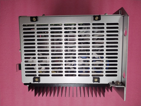
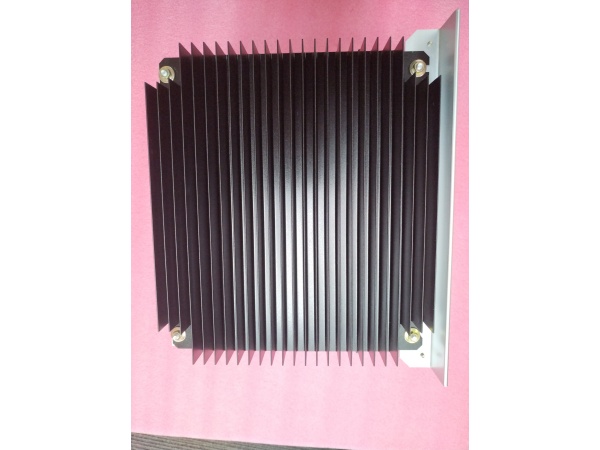
- Forced-air cooling system removes heat from IGBT modules and heatsinks
- High-Speed Serial Link (HSSL) provides bidirectional communication with EX2100e control processor
- Protection circuits include IGBT snubbers, DC leg fuses, and overcurrent detection
- Secondary DC input (125-250V battery) provides diode-isolated backup power
- Control interface connects to EX2100e UCSB for closed-loop regulation and diagnostics
GE 151X1235DB15SA02
Field Service Pitfalls: What Rookies Get Wrong
Mixing Old and New PCM Versions
The older SA01 PCM uses Powerex CM50TL-24NF IGBTs, while upgraded versions (including SA02 variants) use new IGBT modules requiring ControlST V07.04.00C or higher. Mixing these in warm backup configurations causes software incompatibility and control failures.
Field Rule: NEVER mix old-style PCM (SA01) with new upgraded PCM in the same EX2100e system. The ControlST software version must match the PCM hardware. Always verify PCM revision and ControlST version compatibility before installation or replacement.
Incorrect AC Input Connection
The PCM accepts 90-280V AC input from multiple sources. Connecting to the wrong source or applying 480V AC intended for 120A systems destroys the input stage immediately.
Quick Fix: Verify the input source voltage matches the 90-280V range for 35A systems. Use a multimeter to measure AC voltage at the PCM input terminals before energizing. Check system single-line drawings to confirm the correct power source (PMG vs. auxiliary bus vs. generator terminals).
Ignoring Battery Backup Polarity
The secondary DC input (125-250V battery) provides diode-isolated backup power. Reversing polarity during connection bypasses the isolation diode and can damage the DC link circuitry.
Field Rule: Always verify battery polarity with a multimeter before connecting to the PCM DC input terminals. The positive terminal must connect to the PCM positive input, negative to negative. The diode isolation only protects against reverse voltage from the PCM side—external reversal causes damage.
Overlooking DC Link Pre-charge
During startup or after maintenance, the DC link capacitors need controlled pre-charge to prevent inrush current damage. Applying full AC power without verifying pre-charge circuit operation stresses input components.
Quick Fix: In systems with pre-charge resistors, ensure the pre-charge cycle completes before applying full AC power. Monitor DC link voltage during startup—it should rise smoothly to expected levels. Sudden voltage jumps indicate pre-charge failure.
Insufficient Cooling Airflow
The PCM requires forced-air cooling for IGBT heat dissipation. Blocking cabinet airflow with cables or failing to verify fan operation causes thermal trips and IGBT failure.
Field Rule: Ensure cabinet cooling fans are operational before energizing the PCM. Maintain minimum clearance around air intake and exhaust vents. Monitor PCM temperature during commissioning—alarm levels typically trigger at 80-90°C, trip levels higher. Clean air filters regularly to maintain airflow.
Neglecting Output Shunt Calibration
The output shunt provides field current feedback for control regulation. Replacing the PCM without verifying shunt calibration causes current measurement errors and poor voltage regulation.
Field Rule: When replacing the PCM, verify the output shunt calibration matches the EX2100e controller configuration. Use the EX2100e toolbox to compare measured field current against a reference ammeter. Recalibrate if deviation exceeds specified tolerance (typically ±1-2%).
Bypassing DC Contactor Interlock
The PCM output flows through a DC contactor to the exciter field. Bypassing the contactor or defeating interlocks during troubleshooting exposes personnel to hazardous DC voltages.
Field Rule: Never bypass safety interlocks or the DC output contactor. Follow proper lockout/tagout (LOTO) procedures before working on the PCM output circuits. The exciter field can carry lethal DC currents even when the generator is offline.
Incorrect Forcing Command Timing
The PCM provides 210% forcing capability for transient response. Applying forcing commands at inappropriate times (such as during steady-state operation) overheats the IGBTs and reduces component life.
Quick Fix: Use forcing only during specified conditions—load rejection, fault recovery, or rapid startup as defined in the EX2100e control logic. Monitor PCM temperature during forcing events. Prolonged forcing above rated current causes thermal stress and premature IGBT failure.
Misdiagnosing DD Circuit Faults
The Dynamic Discharge (DD) circuit limits DC link voltage during transients. Interpreting DD circuit activation as a fault condition and disabling it risks DC link overvoltage damage.
Field Rule: The DD circuit should activate during load rejection, unit trip, or rapid load reduction—this is normal operation. Only investigate DD circuit faults if it triggers during normal steady-state conditions or fails to activate during expected transient events. Check DD resistor continuity and IGBT gating signals.
Forgetting to Update Control Software After PCM Upgrade
When upgrading to new PCM versions, the EX2100e ControlST software must be updated to V07.04.00C or higher. Installing the new PCM without software updates causes communication failures and erratic control behavior.
Field Rule: Always check ControlST software version compatibility before replacing a PCM. Upgraded PCMs require specific minimum ControlST versions. Plan for software backup, update, and parameter restoration as part of any PCM replacement procedure. Document all pre-existing control constants before software updates.
Improper Grounding of Bridge Interface
The PCM bridge interface subsystem requires proper grounding for EMI suppression and safety. Leaving grounding loose or disconnected causes noise issues and potential safety hazards.
Quick Fix: Verify all grounding connections on the PCM bridge interface are tight and connected to the cabinet ground bus. Use a torque screwdriver to follow specified torque values. Check ground continuity from PCM chassis to cabinet ground point during commissioning.
Ignoring IGBT Gate Drive Faults
IGBT gate drive faults cause immediate PCM failure. Focusing on power circuit diagnostics while missing early warning signs of gate drive issues leads to catastrophic failures.
Field Rule: Monitor EX2100e diagnostic alarms for gate drive fault indications. These often precede catastrophic IGBT failure. Inspect gate drive connections, check gate resistor values, and verify EGPA (Exciter Gate Pulse Amplifier) board outputs during preventive maintenance.
Commercial Availability & Pricing Note
Please note: The listed price is for reference only and is not binding. Final pricing and terms are subject to negotiation based on current market conditions and availability.


