
Description
Key Technical Specifications
-
Model Number: 151X1235DB15SA02
-
Manufacturer: General Electric (GE)
-
Input Range: 90-280 Vrms, 45-480 Hz (single- or three-phase)
-
Output Rating: 35 A @ 250 Vdc continuous, 120 A ceiling for 10 s
-
Topology: Six-pack IGBT 3-phase inverter; two devices used for PWM dc output, one for dump-resistor discharge
-
Switching Frequency: 40 kHz (max)
-
Response Time: < 1 ms for 90 % step change
-
Efficiency: > 92 % at full load
-
Control Interface: RS-485 Modbus RTU, EtherNet/IP, wired to EX2100e controller
-
Redundancy: Identical M1 (primary) & M2 (backup) modules with auto-transfer
-
Isolation: 2 kV input-to-output, 500 V channel-to-ground
-
Protection: OC, OV, UV, OT, short-circuit, 1500 V surge
-
Operating Temperature: –40 °C…+70 °C
-
Protection Degree: IP20 (module), IP00 heat-sink fins
-
Dimensions / Weight: ≈ 178 × 140 × 50 mm, 0.5 kg

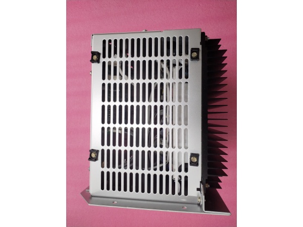
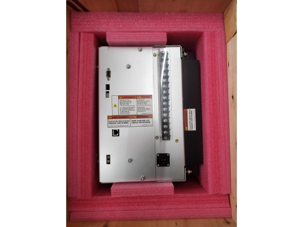
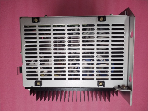
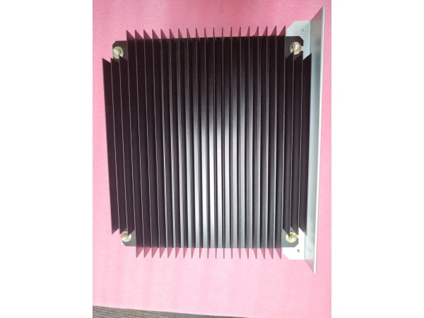
GE 151X1235DB15SA02
Field Application & Problem Solved
EX2100e exciters on 7FA gas turbines need a fast field supply that can slam 35 A into the rotor in < 1 ms to ride through grid faults. Drop the 151X1235DB15SA02 into the M1/M2 slots and the DSP commands the IGBT half-bridge to buck the 280 V PMG feed down to 250 Vdc while keeping ripple below 1 %. I’ve used these on 50 Hz peakers in Kuwait—when the grid threw a 15 % dip the PCM ramped from 20 A to 120 A ceiling in 400 µs, held terminal volts, and saved the block-load. Value: one plug-in module replaces the old thyristor cubicle plus analog regulator, freeing four rack slots and cutting wiring by half.
EX2100e exciters on 7FA gas turbines need a fast field supply that can slam 35 A into the rotor in < 1 ms to ride through grid faults. Drop the 151X1235DB15SA02 into the M1/M2 slots and the DSP commands the IGBT half-bridge to buck the 280 V PMG feed down to 250 Vdc while keeping ripple below 1 %. I’ve used these on 50 Hz peakers in Kuwait—when the grid threw a 15 % dip the PCM ramped from 20 A to 120 A ceiling in 400 µs, held terminal volts, and saved the block-load. Value: one plug-in module replaces the old thyristor cubicle plus analog regulator, freeing four rack slots and cutting wiring by half.
Installation & Maintenance Pitfalls (Expert Tips)
Internal fuse is NOT field-replaceable – A 40 A semiconductor fuse lives inside the potting. Short the output and the module is scrap; always megger the field leads before first power-up
Internal fuse is NOT field-replaceable – A 40 A semiconductor fuse lives inside the potting. Short the output and the module is scrap; always megger the field leads before first power-up
.
Ceiling-limit resistor mandatory on old rotors – Factory allows 120 A for 10 s. On a wire-wound field that is 3× thermal rating. Set P-LIMIT to 35 A or add a 0.2 Ω ceiling resistor or you’ll warp the coils
.
Dump-resistor IGBT must see load – The third IGBT discharges the DC link into an external DD resistor. Forget to wire the resistor and the link OV trips every time you de-energize; the fault latches and you’ll chase “OV FLT” at 2 a.m. .
RS-485 shield grounding – The comm port is isolated, but if you ground the shield at both ends the 40 kHz switching noise rides the shield and you’ll get “Comm-Lost” every time the duty cycle changes. Ground shield at the DCS end only .
GE 151X1235DB15SA02
Technical Deep Dive & Overview
The 151X1235DB15SA02 is a 40 kHz IGBT buck module potted in epoxy and bolted to a steel heat-sink plate. A DSP running at 100 µs loop rate commands the half-bridge while an on-board Hall sensor gives ±0.5 % current feedback. The same DSP talks to the EX2100e controller over RS-485; voltage, VAR, and ceiling-limit set-points arrive every 5 ms and are summed with droop and under-excitation limit logic. Redundancy is inherent—two identical PCMs (M1 & M2) plug into the rack and a transfer module evaluates health; if M1 loses feedback or hits thermal limit the transfer logic masks it and promotes M2 in < 2 ms, keeping the field alive without a bump. No external CTs, no fans—just a 0.5 kg brick you can swap with one hand while the turbine is on turning gear.
The 151X1235DB15SA02 is a 40 kHz IGBT buck module potted in epoxy and bolted to a steel heat-sink plate. A DSP running at 100 µs loop rate commands the half-bridge while an on-board Hall sensor gives ±0.5 % current feedback. The same DSP talks to the EX2100e controller over RS-485; voltage, VAR, and ceiling-limit set-points arrive every 5 ms and are summed with droop and under-excitation limit logic. Redundancy is inherent—two identical PCMs (M1 & M2) plug into the rack and a transfer module evaluates health; if M1 loses feedback or hits thermal limit the transfer logic masks it and promotes M2 in < 2 ms, keeping the field alive without a bump. No external CTs, no fans—just a 0.5 kg brick you can swap with one hand while the turbine is on turning gear.


