
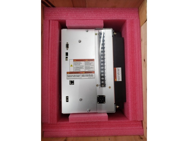
Description
Hard-Numbers: Technical Specifications
- Nominal Output Current: 35A DC continuous
- Forcing Capability: 210% of rated current (73.5A) temporary forcing
- AC Input Range: 90-280V rms, nominal (3-phase or 1-phase)
- AC Input Frequency: Up to 480 Hz
- Secondary DC Input: 125-250V DC (battery backup)
- Output Voltage: Up to 250V DC regulated (field excitation)
- PWM Switching Frequency: ~1,000 Hz
- Power Topology: IGBT-based 3-phase inverter with DC link
- Dimensions: 40 x 45 x 35 cm
- Weight: 8.8 kg
- Ambient Temperature: 0°C to 40°C (derating at 50°C)
- Enclosure Rating: NEMA 1/IP20 or IP21 standard (IP54 optional)
- Communication Protocols: Ethernet LAN, EGD protocol, Modbus TCP/IP
- Control Software Requirement: ControlST V07.04.00C or higher required for upgraded PCM replacement
- Isolation Rating: Per UL508C and EN 50178 for power conversion equipment
- IGBT Module: Powerex CM50TL-24NF (legacy module – obsolete)

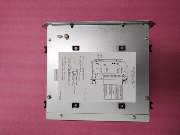
GE 151X1235DB15SA01
The Real-World Problem It Solves
Generator excitation systems need precise, fast-responding DC field current regulation to maintain stable voltage output during load transients, grid faults, and startup sequences. The 151X1235DB15SA01 provides a compact, digitally-controlled power conversion solution that converts AC input into precisely regulated DC excitation current with exceptional dynamic response and forcing capability.
Where you’ll typically find it:
- Gas turbine generators (Frame 5, Frame 6, Frame 7, Frame 9) in combined cycle and simple cycle plants
- Steam turbine generators in utility power plants and industrial cogeneration facilities
- Hydro generators in hydroelectric installations requiring precise excitation control
- EX2100e excitation control cabinets (35A simplex or warm backup configurations)
- Legacy installations using original Powerex IGBT modules before GE upgrade program
Bottom line: It’s a proven power conversion workhorse in GE’s EX2100e digital excitation system—delivering field current that keeps generator voltage stable under any operating condition.
Hardware Architecture & Under-the-Hood Logic
The 151X1235DB15SA01 is a power conversion module combining Powerex CM50TL-24NF IGBT-based PWM inverter technology with digital control interfaces for precise excitation control. It interfaces directly with the EX2100e Universal Controller Stand-alone (UCSB) via High-Speed Serial Link (HSSL) and does not contain its own microprocessor—all control logic resides in the UCSB.
- Three-phase AC input (90-280V rms from PMG, auxiliary bus, or generator terminals) enters through input EMI filters
- Input section consists of 3-phase diode bridge rectifier with line reactors for current limiting
- DC link capacitors store energy and provide smooth DC bus voltage for IGBT inverter
- Dynamic Discharge (DD) circuit limits DC link voltage during load rejection or unit trip events
- IGBT inverter bridge (6 Powerex CM50TL-24NF devices in 3-phase configuration) PWM-modulates DC link at ~1,000 Hz
- Output section feeds regulated DC to exciter field through DC contactor and output shunt
- Output shunt monitors field current for feedback control to UCSB controller
- Gate Pulse Amplifier board (EGPA) receives firing signals from UCSB and drives IGBT gates
- Thermistor monitors PCM temperature for alarm/trip functions communicated via HSSL
- Bridge Interface subsystem includes AC filters, DC filters, and isolation devices
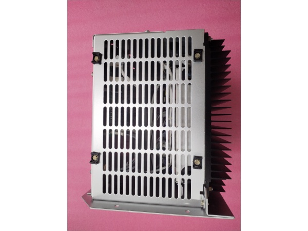
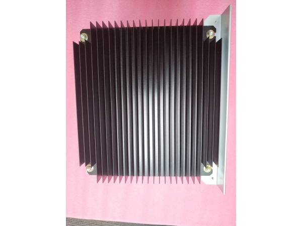
- Forced-air cooling system removes heat from Powerex IGBT modules and heatsinks
- High-Speed Serial Link (HSSL) provides bidirectional communication with EX2100e control processor
- Protection circuits include IGBT snubbers, DC leg fuses, and overcurrent detection
- Secondary DC input (125-250V battery) provides diode-isolated backup power
- Control interface connects to EX2100e UCSB for closed-loop regulation and diagnostics
GE 151X1235DB15SA01
Field Service Pitfalls: What Rookies Get Wrong
Forcing New IGBTs into Legacy SA01 PCM
The SA01 PCM was designed specifically for Powerex CM50TL-24NF IGBTs. Newbies attempt to retrofit newer IGBT modules into the SA01 chassis, expecting improved performance without upgrading the entire PCM assembly to SA02/SA03 specifications.
Field Rule: DO NOT attempt to retrofit newer IGBT modules into the legacy SA01 PCM. The gate drive circuits, snubber networks, and thermal interface were designed for the Powerex CM50TL-24NF characteristics. If replacement is needed, upgrade the entire PCM to the current revision (SA02 or SA03), which requires updating ControlST to V07.04.00C or higher.
Ignoring IGBT Obsolescence Warnings
The Powerex CM50TL-24NF IGBT module used in the SA01 is obsolete. Newbies stock only the SA01 PCM without securing spare IGBTs, leaving the plant vulnerable to extended downtime when IGBTs fail and cannot be sourced.
Quick Fix: If you have SA01 PCMs in inventory, source Powerex CM50TL-24NF IGBTs or compatible equivalents immediately. Better yet—budget for PCM upgrades to SA02/SA03 versions that use readily available IGBT modules. The cost of extended downtime during an excitation failure far exceeds the PCM upgrade cost.
Mixing SA01 and Upgraded PCM in Warm Backup
The EX2100e warm backup configuration uses two independent PCMs. Newbies install an upgraded SA02 PCM alongside a legacy SA01 PCM, expecting them to operate together seamlessly.
Field Rule: NEVER mix SA01 with SA02/SA03 PCMs in warm backup configuration. The ControlST software versions are incompatible, gate drive characteristics differ, and forcing capabilities may not match. Both PCMs must be the same revision. If upgrading, replace both PCMs simultaneously and update ControlST to V07.04.00C or higher.
Overlooking Thermal Paste Degradation
The Powerex IGBT modules mount to heatsinks with thermal interface material. Newbies pull and reinstall IGBTs without cleaning old thermal paste and applying fresh compound, causing thermal runaway and premature failure.
Field Rule: When servicing IGBTs, always remove all old thermal paste from both the IGBT baseplate and heatsink surface using isopropyl alcohol. Apply fresh, high-quality thermal compound (preferably non-silicone based) in a thin, even layer. Use a torque wrench to tighten IGBT mounting bolts to specification—over-torquing cracks the IGBT package, under-torquing causes poor thermal contact.
Incorrect Gate Resistance Measurements
Powerex CM50TL-24NF IGBTs require specific gate resistors for proper switching characteristics. Newbies assume all gate resistors are equal and install incorrect values when replacing EGPA boards.
Quick Fix: Verify gate resistor values against the SA01 PCM schematic before replacement. Measure resistances in-circuit with a quality multimeter. Incorrect gate resistance causes slow switching (overheating) or fast switching (voltage spikes that destroy the IGBT). Document the original resistor values—they’re often hand-selected during factory calibration.
Neglecting Snubber Circuit Inspection
The IGBT snubber circuits (RC networks) protect Powerex devices from voltage spikes during switching. Newbies focus only on the IGBTs themselves, leaving degraded snubber resistors or capacitors in place.
Field Rule: Inspect ALL snubber components when servicing the SA01 PCM. Look for cracked resistor bodies, bulging capacitors, or solder joint fatigue. A failed snubber circuit lets voltage spikes reach the IGBT, causing catastrophic failure during normal switching events. Replace snubber resistors and capacitors as a set—never mix old and new components in the same snubber network.
Bypassing the DD Resistor During Testing
The Dynamic Discharge (DD) resistor dissipates DC link energy during transients. Newbies disconnect the DD resistor to simplify troubleshooting, leaving the DC link unprotected during testing.
Field Rule: NEVER disable the DD resistor circuit, even for bench testing. The DC link capacitors store lethal energy that must be safely dissipated. A disconnected DD circuit causes voltage spikes during IGBT switching that can destroy the DC link capacitors and IGBTs. If the DD resistor is open circuit, replace it with the correct power rating and resistance value.
Assuming All SA01 PCMs Are Identical
Early production SA01 PCMs have board-level revisions that affect component placement and wiring. Newbies swap SA01 PCMs from different production runs without verifying internal compatibility.
Quick Fix: Always compare the SA01 PCM board revision numbers and internal wiring before interchange. Document the exact PCM revision installed in each EX2100e cabinet. If board revisions differ, verify that the EX2100e parameter file matches the specific PCM revision. A mismatch causes erratic control behavior and potential IGBT damage.
Failing to Pre-charge DC Link After Service
After capacitor or IGBT replacement, the DC link needs controlled pre-charge. Newbies apply full AC power immediately after service, causing inrush current that stresses newly installed components.
Field Rule: Follow the EX2100e pre-charge procedure after any PCM service. Monitor DC link voltage during startup—it should ramp smoothly to nominal levels. Sudden voltage jumps indicate insufficient pre-charge time or failed pre-charge resistors. Use the EX2100e toolbox to verify DC link voltage stability before enabling output to the exciter field.
Ignoring Legacy Software Compatibility
The SA01 PCM was designed for earlier ControlST versions. Newbies upgrade ControlST to the latest version without verifying backward compatibility with the legacy SA01 hardware.
Field Rule: If you must retain the SA01 PCM, verify ControlST version compatibility with the specific PCM revision. Some newer ControlST versions may not support the SA01 gate drive characteristics. The safe path: upgrade to SA02/SA03 PCM and ControlST V07.04.00C or higher together. Mixing unsupported software with legacy hardware causes unpredictable excitation control behavior.
Commercial Availability & Pricing Note
Please note: The listed price is for reference only and is not binding. Final pricing and terms are subject to negotiation based on current market conditions and availability.
CRITICAL OBSOLESCENCE WARNING: The 151X1235DB15SA01 PCM contains the Powerex CM50TL-24NF IGBT module, which is obsolete and increasingly difficult to source. GE has upgraded the EX2100e 35A PCM to newer revisions (SA02, SA03) that use readily available IGBT modules. Inventory of new SA01 PCMs is extremely limited. When SA01 PCMs require replacement, consider upgrading to the current PCM revision and updating ControlST software to V07.04.00C or higher. Retrofitting new IGBTs into legacy SA01 chassis is not supported by GE and voids warranties.


