
Description
Hard-Numbers: Technical Specifications
- Pipe Size Range: 2″ to 36″ (DN50 to DN900)
- Flow Range: 0.5-20 ft/s (0.15-6 m/s) velocity
- Typical Flow Rate (8″ pipe): 50-500 GPM (190-1890 LPM)
- Accuracy: ±2% of reading
- Repeatability: ±0.5% of reading
- Pressure Rating: ANSI 150# at 70°F (21°C)
- Material: 316 Stainless Steel paddle, PVC or PVDF body
- Operating Temperature: 0°C to 60°C (32°F to 140°F) wetted parts
- Output Signal: Pulse output (hall effect) or 4-20 mA (loop-powered)
- Frequency Range: 0-200 Hz (typical K-factor 10 pulses/ft/s)
- Connection Type: 2″ NPT female hot tap or compression fitting
- Fluid Compatibility: Clean liquids, viscosity up to 25 cSt
- Minimum Straight Run: 10x pipe diameter upstream, 5x downstream
- Insertion Depth: Adjustable, typically center of pipe
- Cable Length: Standard 15 ft (4.6 m), extendable to 50 ft

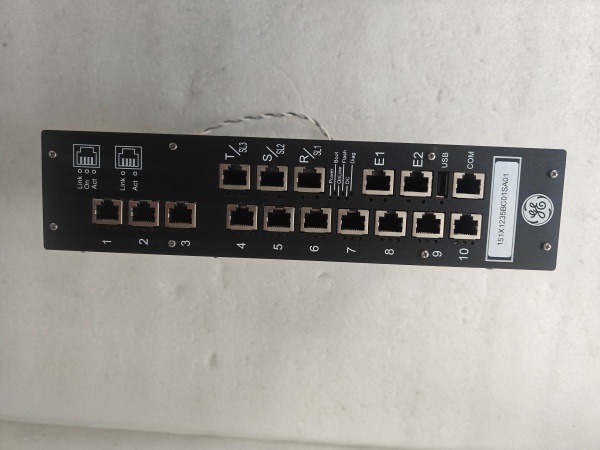
GE 151X1235BC01SA01
The Real-World Problem It Solves
Full-bore meters on large pipes cost thousands. The 151X1235BC01SA01 inserts through a 2″ tap, providing flow measurement at a fraction of the cost without cutting the pipe or shutting down process.
Where you’ll typically find it:
- Cooling water and process water monitoring
- Chemical feed and dosing lines
- Wastewater treatment influent/effluent monitoring
- Irrigation and water distribution systems
Bottom line: Low-cost insertion flow measurement for large pipes without shutdown.
Hardware Architecture & Under-the-Hood Logic
Paddle wheel meters use a small rotor with blades inserted into the flow stream. Fluid flow causes the paddle to rotate at a speed proportional to flow velocity. A Hall effect sensor detects paddle rotation and generates electrical pulses. For 4-20mA variants, an internal microcontroller converts pulse frequency to current output proportional to flow rate. The paddle can be inserted and removed under pressure using a hot tap assembly.
Signal flow:
- Fluid flows past inserted paddle wheel
- Paddle rotates at speed proportional to flow velocity
- Hall effect sensor detects each paddle blade passage
- Sensor generates electrical pulse for each revolution
- Pulse frequency correlates to flow velocity via K-factor
- For 4-20mA variants, microcontroller converts frequency to current
- Current loop driver outputs 4-20 mA proportional to flow rate
- Pulses or 4-20 mA transmitted to PLC/totalizer
- Hot tap assembly allows insertion/removal under pressure
GE 151X1235BC01SA01
Field Service Pitfalls: What Rookies Get Wrong
Incorrect insertion depth causes measurement errorsThe paddle must be at the pipe center for accurate velocity measurement. I’ve seen technicians install paddles too shallow, reading 20-30% low due to velocity profile variations near the pipe wall.
- Field Rule: Calculate insertion depth based on pipe OD and wall thickness. Use the depth marking on the insertion probe. For turbulent flow (Re > 4000), center the paddle at 50% of pipe ID. Verify insertion depth during commissioning by retracting and re-inserting the paddle. Document the exact insertion depth in your installation records.
Air bubbles and turbulence cause erratic readingsEntrained air strikes the paddle, causing erratic rotation. I’ve seen paddle wheels spin wildly on bubbly lines, triggering false high flow alarms.
- Field Rule: Install the paddle at least 20 pipe diameters downstream of pumps or elbows to allow flow to stabilize. Mount the insertion assembly at the 10 o’clock or 2 o’clock position to minimize air bubble impact. Install an air eliminator upstream if necessary. Test operation at various flow rates—erratic readings indicate turbulence or air entrainment.
Forgotten to verify pipe size affects K-factorThe K-factor changes with pipe diameter. I’ve seen technicians use the default 8″ pipe K-factor on 12″ pipe, causing flow errors up to 30%.
- Field Rule: Calculate the K-factor based on actual pipe ID. Use the manufacturer’s K-factor calculator or formula: K = (Pipe Area × Conversion Factor). For paddle wheel meters, K-factor is typically 10 pulses/ft/s × Pipe Area (ft²). Document the pipe size and calculated K-factor in your calibration records. Re-calculate if pipe size changes.
Chemical compatibility issues with wetted materialsThe paddle material must match process fluid. I’ve seen technicians install standard PVC paddles in aggressive chemical lines, causing paddle degradation and failure within weeks.
- Field Rule: Verify wetted material compatibility (PVC, PVDF, 316 SS paddle) with process fluid. Check chemical compatibility charts for temperature and concentration. For aggressive chemicals, specify PVDF or all 316 SS construction. Replace the paddle at first signs of swelling, cracking, or discoloration.
Improper hot tap operation causes process leaksRemoving the paddle under pressure requires proper hot tap procedure. I’ve seen technicians retract the paddle without closing the isolation valve, causing process fluid to spray.
- Field Rule: Close the isolation valve before retracting the paddle. Verify zero pressure at the insertion port before removing the paddle assembly. Use appropriate PPE (face shield, gloves) when working under pressure. Never force the retraction mechanism—if stuck, shut down the line and troubleshoot. Document hot tap procedures and train all technicians.
Temperature limits exceeded causes paddle deformationPVC and plastic materials soften at elevated temperatures. I’ve seen technicians install standard PVC paddles on 80°F lines, causing the paddle to warp and bind.
- Field Rule: Verify the maximum temperature rating for the paddle material (PVC: 140°F, PVDF: 180°F). For high-temperature applications (>140°F), specify all 316 SS construction. Monitor process temperature continuously—install a high-temperature alarm if needed. Replace the paddle immediately if deformation is observed.
Forgotten to account for velocity profile distortionsFlow disturbances near elbows, valves, and tees distort the velocity profile. I’ve seen paddle wheels installed 3 pipe diameters downstream of an elbow, causing ±10% flow errors.
- Field Rule: Maintain minimum 10x pipe diameter straight run upstream and 5x downstream of the paddle. If space is tight, install a flow straightener or relocate the insertion assembly. Verify flow profile stability by testing at multiple flow rates and checking for repeatability. Document straight run distances in your installation records.
Commercial Availability & Pricing Note
Please note: The listed price is for reference only and is not binding. Final pricing and terms are subject to negotiation based on current market conditions and availability.


