
Description
Hard-Numbers: Technical Specifications
- DP Range: 0-100 inH2O (0-249 mbar)
- Static Pressure Rating: 2000 psig (138 bar) continuous
- Output Signal: 4-20 mA (2-wire loop-powered)
- Communication: HART Protocol (digital superimposed on 4-20 mA)
- Accuracy: ±0.075% of calibrated span
- Long-Term Stability: ±0.1% per year
- Supply Voltage: 10-35 VDC
- Load Resistance: 0-750 Ω @ 24 VDC
- Process Connection: 1/2″ NPT female (dual ports)
- Wetted Material: 316 Stainless Steel diaphragms
- Electrical Connection: 1/2″ NPT conduit entry
- Operating Temperature: -40°C to 85°C (-40°F to 185°F)
- Compensated Temperature: -10°C to 80°C (14°F to 176°F)
- Enclosure Rating: NEMA 4X (IP66) polycarbonate housing
- Response Time: <100 ms
- Safety Certification: SIL 2 capable, CSA, CE, ATEX
- Zero/Span Adjustment: Digital via HART
- Weight: 2.0 lbs (0.9 kg)

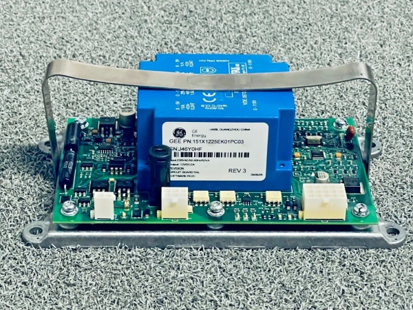
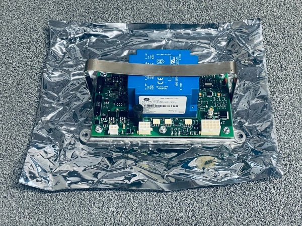
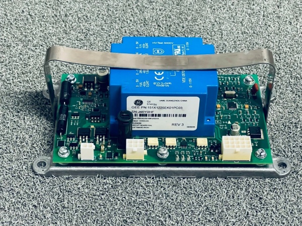
GE 151X1225EK01PC03
The Real-World Problem It Solves
Flow measurement using orifice plates requires precise differential pressure measurement. The 151X1230BR02SA02 provides continuous DP feedback with square root extraction for volumetric flow calculation, enabling accurate flow monitoring without costly Coriolis meters.
Where you’ll typically find it:
- Orifice plate flow measurement (liquid, gas, steam)
- Open tank level measurement (bubbler or wet leg)
- Filter differential pressure monitoring
Bottom line: Differential pressure measurement for flow, level, and filter status with smart diagnostics.
Hardware Architecture & Under-the-Hood Logic
This transducer uses two 316SS diaphragms isolated from each other. Differential pressure deflects both diaphragms equally, with the deflection transferred to a capacitive sensor element. A capacitance-to-digital converter measures the capacitance change, which is proportional to differential pressure. An internal ASIC conditions the signal and outputs a 4-20 mA current proportional to DP. HART modem superimposes digital communication for configuration and diagnostics. Non-volatile memory stores calibration, configuration, and diagnostic data.
Signal flow:
- Differential pressure applied to high and low pressure ports
- Diaphragms deflect proportionally to DP
- Capacitive sensor measures diaphragm position
- Capacitance-to-digital converter outputs digital value
- Signal conditioning ASIC compensates for temperature and static pressure
- Square root extraction enabled for flow applications
- Current loop driver outputs 4-20 mA proportional to DP or flow
- HART modem adds FSK digital signal to analog loop
- Output terminals deliver 4-20 mA + HART to control system
GE 151X1225EK01PC03
Field Service Pitfalls: What Rookies Get Wrong
Reverse static pressure damages the diaphragmHigh static pressure on the low side can reverse bias the diaphragm. I’ve seen technicians reverse connections, causing diaphragm rupture and complete failure.
- Field Rule: Identify high pressure and low pressure ports. High port connects to upstream side (e.g., orifice inlet, tank bottom). Low port connects to downstream side (e.g., orifice outlet, vapor space). Label both connections clearly during installation. Verify DP polarity during commissioning—positive DP should read positive mA. Install isolation valves and equalization valve for zeroing.
Single-seal liquid level measurement causes calibration driftUsing a single seal pot for wet leg reference introduces height errors. I’ve seen technicians ignore the reference leg height, causing level errors up to 10% of span.
- Field Rule: For wet leg level measurement, use a 5-point calibration with actual liquid height. Compensate for reference leg height in the transmitter configuration. Use a 2-point or 5-point calibration for dry leg (closed tank) applications. Document the reference leg height and specific gravity in your calibration records. Re-zero after temperature changes or process shutdowns.
Condensate buildup causes DP biasCondensate in the impulse lines creates hydrostatic head errors. I’ve seen technicians ignore condensate in steam flow applications, causing flow readings 5-15% high.
- Field Rule: Install condensate pots at the same elevation on both impulse lines. Maintain equal liquid levels in both pots. For steam applications, use steam tracing to keep impulse lines above condensation point. Purge impulse lines regularly or install seal pots to prevent condensate accumulation. Document condensate pot elevations and specific gravity.
Impulse line blockage causes zero shiftParticulates or wax buildup blocks impulse lines. I’ve seen DP transmitters reading zero due to completely plugged impulse lines on dirty service applications.
- Field Rule: Install impulse lines with minimum slope (1:12) toward the process for liquids, toward the transmitter for gases. Use minimum 1/4″ tubing size to reduce plugging. Install isolation valves with bleed ports for purging impulse lines. For dirty services, consider seal pots or chemical seals. Monitor DP zero shift over time—increasing zero shift indicates partial blockage.
Over-tightening impulse connections causes zero shiftThe 1/2″ NPT threads can stress the process flange. I’ve seen technicians over-tighten impulse fittings, causing mechanical stress on the sensor and zero shifts up to 2%.
- Field Rule: Use thread sealant and torque to 15 ft-lbs maximum. Never use a cheater bar. Use a torque wrench if available. Install impulse line supports to prevent stress on the process connections. Check zero calibration after installation—if zero has shifted, relieve stress on fittings and re-zero. Document zero readings before and after installation.
Incorrect square root extraction causes flow errorsEnabling square root extraction on non-flow applications creates non-linear output. I’ve seen technicians enable square root on filter DP, causing the output to be the square root of the actual DP.
- Field Rule: Enable square root extraction only for orifice, venturi, or pitot tube flow applications. Disable square root for filter DP and level applications. Test operation by applying a known DP (e.g., 25% of span) and verifying the output is 50% of span with square root enabled (square root of 0.25 = 0.50). Document square root status in your configuration records.
Ignoring HART alarmsThe transmitter provides rich diagnostic data. I’ve seen technicians ignore alarms like “sensor drift” or “temperature out of range,” leading to unexpected failures and downtime.
- Field Rule: Read HART diagnostics weekly or monthly via AMS or handheld communicator. Monitor sensor status, temperature, and electronics health. Look for warnings and alarms—address immediately, not during the next scheduled shutdown. Create a trend log of key parameters (e.g., PV, sensor temperature, static pressure) and review trends for anomalies. Replace transmitters at end-of-life or when diagnostics indicate degradation.
Commercial Availability & Pricing Note
Please note: The listed price is for reference only and is not binding. Final pricing and terms are subject to negotiation based on current market conditions and availability.


