
Description
Hard-Numbers: Technical Specifications
- Pipe Size: 2 inches (DN50)
- Flow Range: 10-100 GPM (38-380 LPM)
- Accuracy: ±0.5% of reading
- Repeatability: ±0.1% of reading
- Pressure Rating: ANSI 150# (PN16)
- Material: Stainless Steel 316L body and rotor
- Operating Temperature: -20°C to 120°C (-4°F to 248°F)
- Output Signal: Pulse output (reed switch or Hall effect)
- Frequency Range: 0-1000 Hz (typical K-factor 100 pulses/gallon)
- Connection Type: Flanged (ANSI 150# RF)
- Fluid Compatibility: Clean liquids, viscosity up to 20 cSt
- Minimum Straight Run: 10x pipe diameter upstream, 5x downstream
- Cable Length: Maximum 50 ft (15 m) for pulse signal

UR-SHA

The Real-World Problem It Solves
Magmeters fail on hydrocarbon-based fluids due to low conductivity. Turbine meters measure actual volumetric flow with pulse output for batching and totalization, ideal for fuel transfer, chemical dosing, and clean liquid applications.
Where you’ll typically find it:
- Fuel transfer and custody transfer systems
- Chemical injection lines
- Water treatment and filtration systems
Bottom line: High accuracy flow measurement for clean liquids with pulse output for precise control.
Hardware Architecture & Under-the-Hood Logic
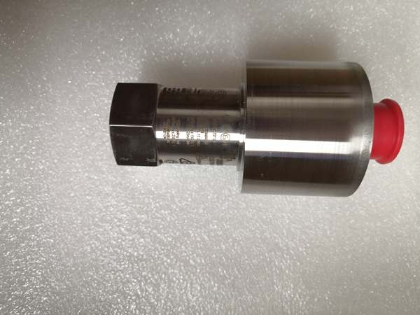
Turbine meters consist of a freely rotating rotor with blades positioned in the flow stream. Fluid flow causes the rotor to spin at a speed proportional to flow velocity. Magnetic or Hall effect sensors detect rotor rotation and generate electrical pulses. The pulse frequency is directly proportional to flow rate; total pulses accumulated equal total volume.
Signal flow:
- Fluid flows through meter body, striking rotor blades
- Rotor begins rotating at speed proportional to flow velocity
- Magnetic sensor (reed switch or Hall effect) detects each blade passage
- Sensor generates electrical pulse for each rotor revolution
- Pulse frequency correlates to flow rate via K-factor
- Pulses transmitted to PLC/totalizer for rate calculation and totalization
- Meter body provides rigid mounting and laminar flow path
- No external power required for pulse generation

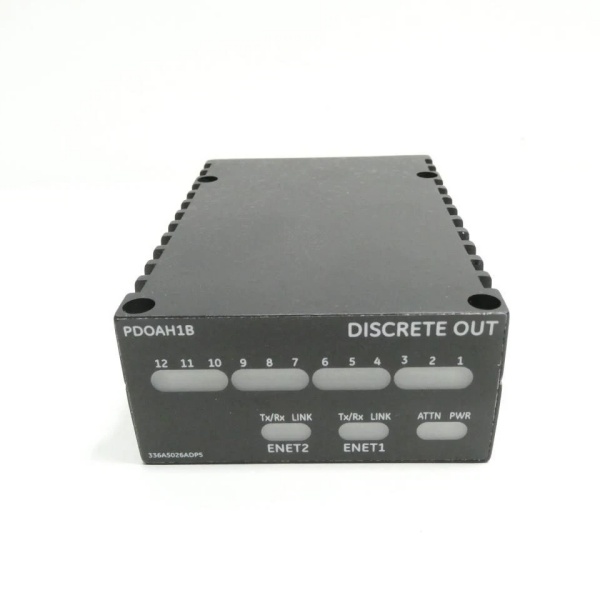
GE IS220PDOAH1B
Field Service Pitfalls: What Rookies Get Wrong
Dirty fluids cause bearing wear and rotor failureTurbine meters need clean fluids. I’ve seen technicians install them in slurry lines, destroying the rotor and bearings within weeks.
- Field Rule: Install a strainer upstream with mesh size appropriate for your fluid. Monitor pressure drop across the meter—increasing ΔP indicates bearing wear. For dirty fluids, consider a magmeter or ultrasonic meter instead. Document cleaning and replacement intervals.
Incorrect mounting orientation affects accuracyThese meters must be installed with flow direction arrow aligned. I’ve seen backwards installations causing rotor binding and zero flow indication.
- Field Rule: Verify flow direction arrow on meter body matches actual flow. Install horizontal or vertical (upward flow) orientation only—downward flow causes poor performance. Ensure full pipe flow at all times. Use isolation valves for maintenance access without process shutdown.
Air bubbles cause erratic pulse generationEntrained air bubbles strike the rotor, causing erratic rotation and pulse spikes. I’ve seen batch systems overfill due to air-induced pulse bursts.
- Field Rule: Install an air eliminator upstream of the meter. Maintain minimum backpressure (>10 psig) to prevent cavitation. Mount the meter in a vertical pipe section with upward flow to help air rise and escape. For gas-liquid mixtures, use a Coriolis meter instead.
Electrical noise affects pulse countingThe pulse signal is susceptible to EMI. I’ve seen pulse counts corrupted by VFDs and variable frequency drives, causing totalization errors.
- Field Rule: Use shielded twisted pair cable for pulse signal, grounded at one end. Keep pulse wiring away from power cables and VFD outputs. Route cable in metallic conduit if possible. Test the pulse signal with an oscilloscope—look for clean square waves. Consider a signal conditioner if noise is unavoidable.
Temperature extremes affect K-factor accuracyThe K-factor (pulses per unit volume) changes with temperature. I’ve seen technicians use a single K-factor across wide temperature ranges, causing flow errors up to 2%.
- Field Rule: Determine the K-factor at your operating temperature range. Use the manufacturer’s temperature compensation curve if available. Document the K-factor and temperature for your specific application. For critical applications, perform an in-situ calibration at operating temperature.
Forgotten to account for viscosity changesHigher viscosity slows rotor speed, causing under-reading. I’ve seen technicians apply water calibration to oil applications, resulting in significant flow errors.
- Field Rule: Apply viscosity correction if your fluid viscosity varies significantly. Use manufacturer’s viscosity correction charts. Consider a Coriolis meter for wide viscosity ranges. Test the meter with actual process fluid during commissioning.
Commercial Availability & Pricing Note
Please note: The listed price is for reference only and is not binding. Final pricing and terms are subject to negotiation based on current market conditions and availability.


